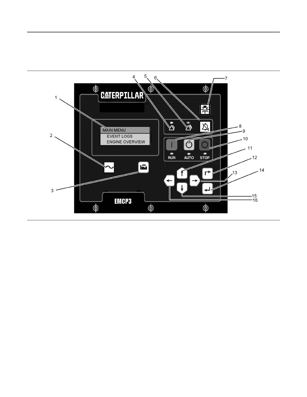
Electronic Control Module (Generator
Set)
Illustration 71 g01045431
(1) Display Screen
(2) AC Overview Key
(3) Engine Overview Key
(4) Yellow Warning Lamp
(5) Red Shutdown Lamp
(6) Alarm Acknowledge Key
(7) Lamp Test Key
(8) Run Key
(9) Auto Key
(10) Stop Key
(11) Up Key
(12) Escape Key
(13) Right Key
(14) Enter Key
(15) Down Key
(16) Left Key
Navigation Keys
AC Overview (2) – The “AC OVERVIEW” key will
navigate the display to the first screen of AC
information. The “AC OVERVIEW” information
contains various AC parameters that summarize the
electrical operation of the generator set.
Engine Overview (3) – The “ENGINE OVERVIEW”
key will navigate the display to the first screen of
engine information. The “ENGINE OVERVIEW”
information contains various engine parameters that
summarize the operation of the generator set.
Acknowledge Key (6) – Pressing the
“ACKNOWLEDGE” key will cause the horn relay to
turn off. This will silence the horn. Pressing this key
will also cause any red or yellow flashing lights to
either turn off or to come on continuously, depending
on the active status of the alarms. The
“ACKNOWLEDGE” key may also be configured to
send out a global alarm silence on the J1939 Data
Link, which will silence the horns on the
annunciators.
Lamp Test Key (7) – Pressing and holding the
“LAMP TEST” key will cause each LED and the
display screen pixels to turn on continuously until the
key is released.
RUN Key (8) – Pressing the “RUN” key will cause the
engine to enter the “RUN” mode.
AUTO Key (9) – Pressing the “AUTO” key will cause
the engine to enter the “AUTO” mode.
STOP Key (10) – Pressing the “STOP” key will cause
the engine to enter the “STOP” mode.
Up Key (11) – The “UP” key is used to navigate
through the various menus and monitoring screens.
The “UP” key is also used when a setpoint is entered.
When entering numeric data, the “UP” key is used in
order to increment the digits (0-9). If the setpoint
SEBU7125-13
61
Operation Section
If Equipped
 Loading...