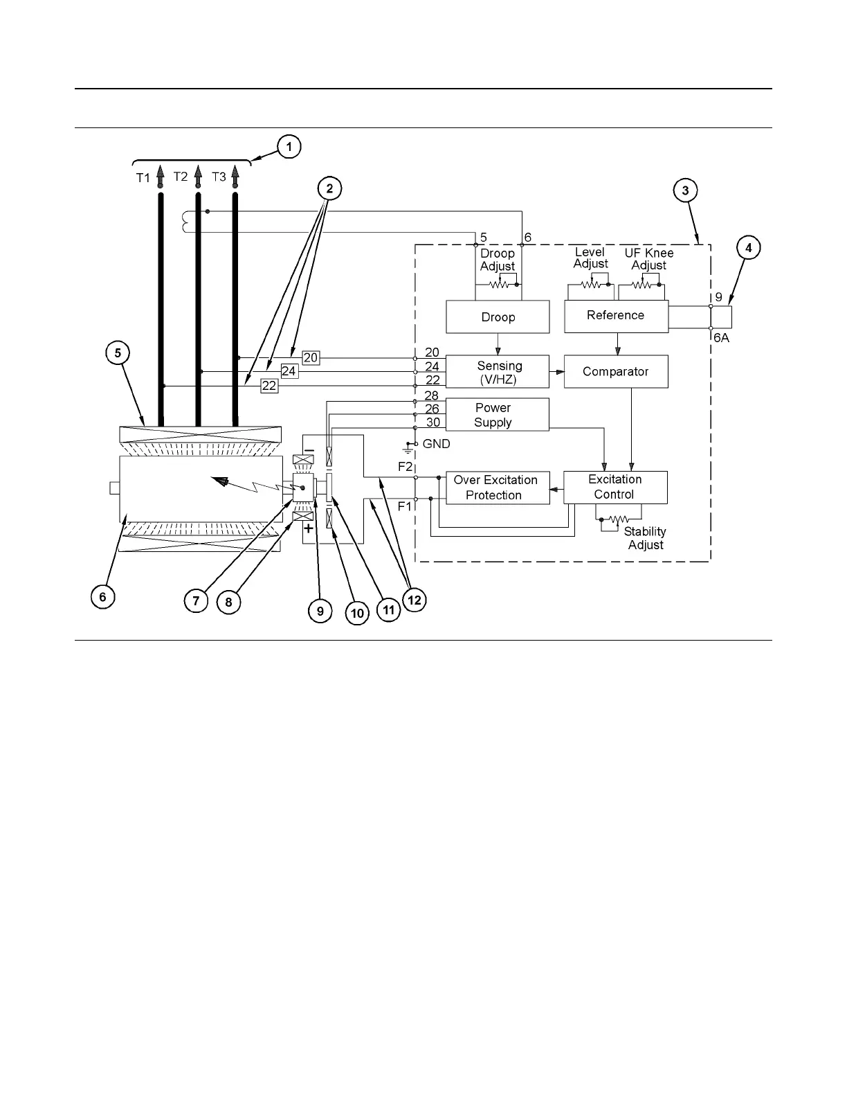
Illustration 83 g02197113
Typical Block Diagram of SR4B Permanent Magnet Permanently Excited (PMPE) Generator with VR6 Voltage
Regulator
(1) Generator lines (output voltage)
(2) Generator lines (sensing voltage and AC
power)
(3) VR6 voltage regulator
(4) Jumper (removed when external voltage
adjust potentiometer is installed)
(5) Main stator
(6) Main rotor
(7) Exciter rotor
(8) Exciter stator
(9) Three-phase rectifiers
(10) Permanent magnet stator
(11) Permanent magnet
(12) Generator lines (DC excitation voltage)
The VR6 voltage regulator is used on 4/6 and 10/12
lead self-excited generators and permanent magnet
generators, and also used on AREP generators. The
VR6 regulator is typically located in the generator
terminal box. The regulator may also be located in
the marshaling box. In some applications, the
regulator may be remotely mounted.
SEBU7125-13
75
Operation Section
Voltage Regulators