Application and Installation Guide EMCP 4 SCADA Data Links
©2013 Caterpillar
All rights reserved. Page 14
T
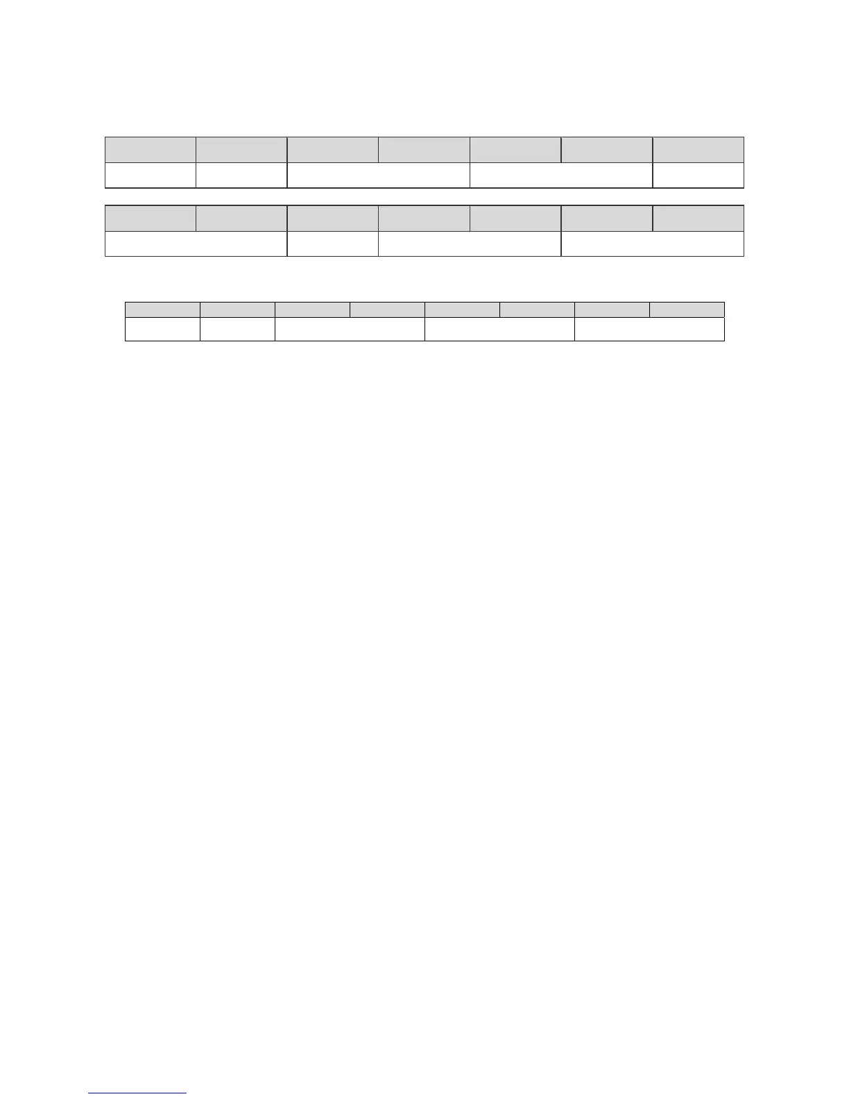
ABLE 4-5: WRITE MULTIPLE REGISTERS - REQUEST
Address Fcn Code Addr hi Addr lo Num hi Num lo Byte Ct
Slave addr. 0x10 Reg address Number of Registers (N) N x 2
Data 1 hi Data 1 lo … Data N hi Data N lo CRC lo CRC hi
Register 1 data … Register N data CRC16 error checking
TABLE 4-6: WRITE MULTIPLE REGISTERS - RESPONSE
Address Fcn Code Addr hi
ddr lo Num hi Num lo CRC lo CRC hi
Slave addr. 0x10 Starting Reg address Number of Registers (N) CRC16 error checking
NOTE: For EMCP 4 controller software version 4.2 PROD and beyond, all control-related write register
capabilities are DISABLED by default. Modbus control via write registers can be enabled by
configuring the “Remote Genset Control Enable Status” setpoint under CONFIGURE > ALL
SETPOINTS > CONTROL > AUTO START/STOP.
4.3 DATA INTERPRETATION
In order to send data, or once data is received, it must be interpreted. A single piece of data can span
multiple Modbus registers. There are a few different types of data:
Numerical data
State-based data
Complex data
On PC systems, register data is converted to numbers according to predefined data types. The EMCP 4
data should always be converted to unsigned data types. The specific data type depends on the PC
system architecture. For example, if UINT data type is 16-bit, then it can be used for single register reads.
For data points that span 2 registers, they must use a longer data type (or calculate the value manually
from two separate UINTs), such as ULONG. But again, the data types available and their length are
system-specific. ULONG may be 32-bit or 64-bit or may not even be supported at all.
If converting the data manually, in order to interpret the data, first the bits must be converted to a raw
number, where the number represents the decimal (base-10) representation of the raw data. Modbus
data is sent most-significant-bit first and most-significant-byte first, and for data spanning multiple
registers, the lowest number register is most significant. The EMCP 4 uses unsigned integer
representations of all the data. Negative values for numerical data are calculated (see Numerical Data
section below) by doing math operations on the unsigned integer value.
Two-register data points should be treated as 4-byte unsigned integers. Example of data received from a
two-register read (spaces added for readability). Note that the response sends the lower number register
first, followed by the higher number register. Therefore, the lower number register is more significant:
Binary data received (in order of receipt): 0b 0000 0000 0000 0000 0000 0110 1000 1111
Raw data in hexadecimal: 0x 0000 068F
Raw data in decimal: 1,679
The rest of the interpretation process depends on the type of data being read.
 Loading...