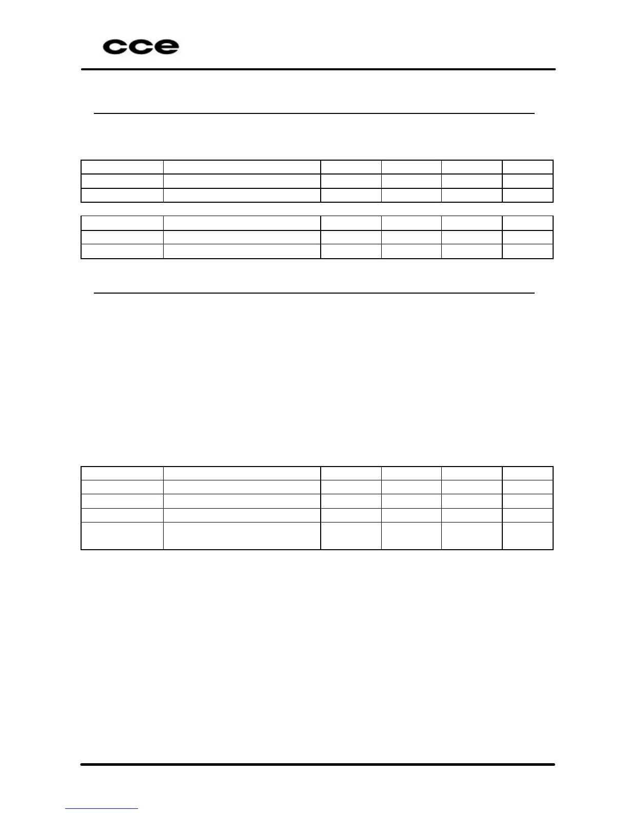
3.2.3 Main Power Supply Regulation with fluctuation of the line
a) Repeat the procedure of the item 2.2 when the television is connected to
the electric net with 100VAC/60Hz and also 240VAC/60Hz.
Condition Test Point Minimum
Unit
“PP” 240V
AC
+B 103V (Cathode of D807) 102.00 103.00 104.00 V
DC
“PP” 240V
AC
+B 16V (Cathode of D808) 14.00 15.50 16.50 V
DC
Condition Test Point Minimum
Unit
“PP” 100V
AC
+B 103V (Cathode of D807) 102.00 103.00 104.00 V
DC
“PP” 100V
AC
+B 16V (Cathode of D808) 14.00 15.50 16.50 V
DC
3.4 Auxiliary power supply from Fly Back Transformer
a) Connect the TV under test to a 117 Vac/60 Hz line.
b) Turn On the TV set and apply a 60dBµV RF signal modulated by a white
pattern video signal and a 4.5 MHz +- 25 kHz deviation FM signal
modulated by a 1kHz audio signal (frequency and channel factory defined).
c) Adjust the TV to a “PP” condition.
d) Utilizing an electronic DC voltmeter (over 10 M input impedance), read the
auxiliary power supply from Fly-Back transformer.
e) Read the RMS voltage apply to the CRT heat. Utilizing a true RMS
voltmeter.
f) When exist, read the auxiliary wind Peak to peak voltage, utilizing an
oscilloscope.
Condition Test Point Minimum
Unit
“PP” 117V
AC
E+12V (Cathode do D402) +11.00 +12.00 +13.00 V
DC
“PP” 117V
AC
E-12V (Anode do D403) -11.00 -12.00 -13.00 V
DC
“PP” 117V
AC
E180V (Anode do D404) 165.00 175.00 185.00 V
DC
“PP” 117V
AC
 Loading...