QUICK START GUIDEQUICK START GUIDE
A22K 2-DOOR / 4-READER CONTROLLERA22K 2-DOOR / 4-READER CONTROLLER
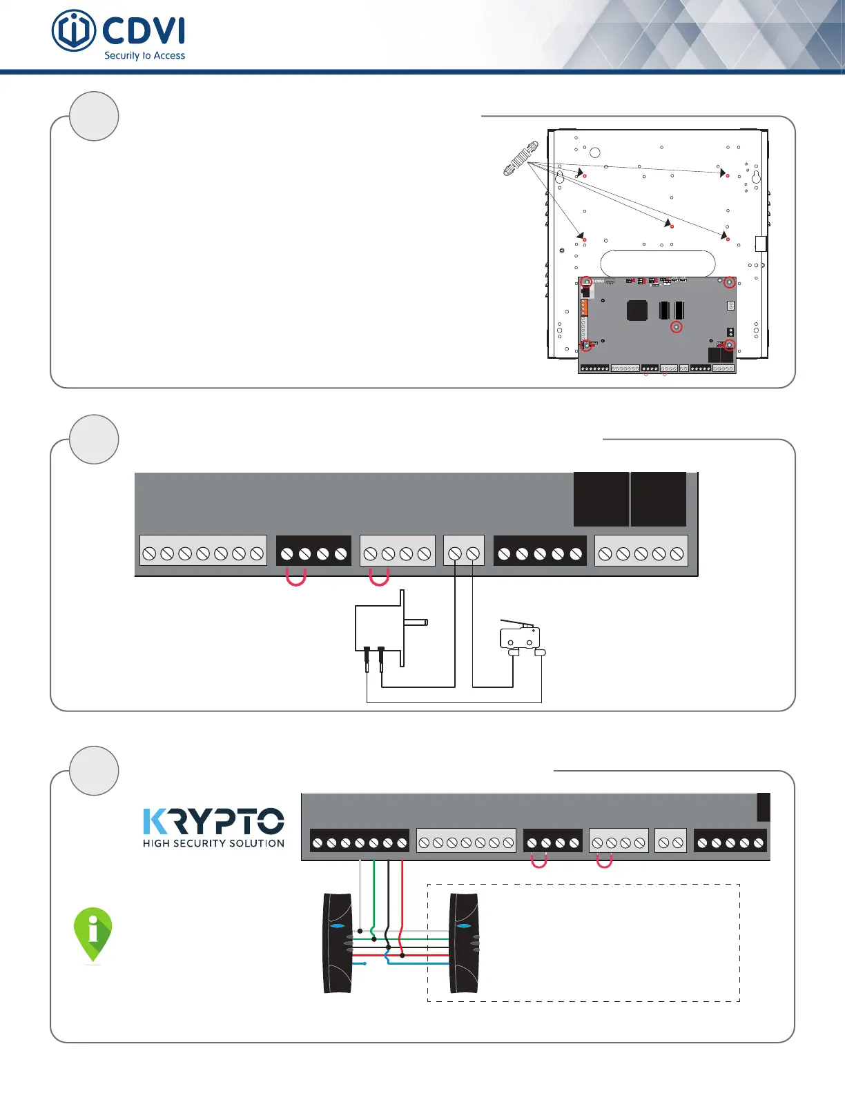
CONNECT THE LOCK
5
+12V DC
+24V DC
-
+12V DC
-
+12V DC
A+
B-
Input 1
Input 2
Output 1
Output 2
INPUT
POWER
SUPPLY
RS485
LOCAL
BUS
ETHERNET
PORT
SYSTEM STATUS
EXTRA
INPUTS/
OUTPUTS
ETHERNET LOCAL BUS LOCK 1 & 2
JUMPER SETTING
STATUS
24V DC INPUT/
BATTERY/
MODULE TYPE
BATTERY
BACKUP
Door Strike
(Door 1)
READER DOOR 1
INPUT
DOOR 1
LOCK
DOOR 1
LOCK
DOOR 2
INPUT
DOOR 2READER DOOR 2
ENCLOSURE
TAMPER
SWITCH
INPUT
BUZ GRN RED D1 D0 GND 12V BUZ GRN RED D1 D0 GND GNDC112V 12VREX1 GND
GND C1 NO1 NC1LK1+ LK1- C2 NO2 NC2LK2+ LK2-TMP
By default, the lock output is set for door strike (“Fail Secure”). The output
is at 0 VDC to keep the door locked and toggles to 12 VDC during 5 sec., on
access granted or request-to-exit, to unlock the door.
The A22K provides 12 VDC/750 mA for each door lock.
CONNECT K1 HIGH SECURITY CARD READER
4
+12V DC
+24V DC
-
+12V DC
-
+12V DC
A+
B-
Input 1
Input 2
Output 1
Output 2
INPUT
POWER
SUPPLY
RS485
LOCAL
BUS
ETHERNET
PORT
SYSTEM STATUS
EXTRA
INPUTS/
OUTPUTS
READER DOOR 1
INPUT
DOOR 1
LOCK
DOOR 1
INPUT
DOOR 2READER DOOR 2
ETHERNET LOCAL BUS LOCK 1 & 2
JUMPER SETTING
STATUS
24V DC INPUT/
BATTERY/
MODULE TYPE
BATTERY
BACKUP
ENCLOSURE
TAMPER
SWITCH
INPUT
Connection shown with
K1 KRYPTO High Security Card Reader
DOOR 1
ENTRY READER
Blue wire NOT connected
DOOR 1
EXIT READER (Optional)
Blue wire connected to A22K GND terminal
(Only required in the need to supervise the exit from an area)
Red
Black
Green
White
BUZ GRN RED D1 D0 GND 12V BUZ GRN RED D1 D0 GND GNDC112V 12VREX1 GND GND C1 NO1 NC1LK1+ LK1-
TMPC2 12VREX2
+12V DC
+24V DC
-
+12V DC
-
+12V DC
A+
B-
Input 1
Input 2
Output 1
Output 2
INPUT
POWER
SUPPLY
RS485
LOCAL
BUS
ETHERNET
PORT
SYSTEM STATUS
EXTRA
INPUTS/
OUTPUTS
ETHERNET LOCAL BUS LOCK 1 & 2
JUMPER SETTING
STATUS
24V DC INPUT/
BATTERY/
MODULE TYPE
BATTERY
BACKUP
READER DOOR 1
INPUT
DOOR 1
LOCK
DOOR 1
LOCK
DOOR 2
INPUT
DOOR 2READER DOOR 2
ENCLOSURE
TAMPER
SWITCH
INPUT
BUZ GRN RED D1 D0 GND 12V
BUZ GRN RED D1 D0 GND GNDC112V 12VREX1 GND GND C1 NO1 NC1LK1+ LK1- C2 NO2 NC2LK2+ LK2-TMPC2 12VREX2
Metal Enclosure
Wall Tamper Switch
(N.C.)
PCB
holder
Metal Enclosure
Door Tamper Switch
(N.C.)
CONNECT METAL ENCLOSURE TAMPER SWITCHES
3
FIX METAL ENCLOSURE & A22K PCB
2
CONNECT THE POWER SUPPLY TERMINAL & BACKUP BATTERY
7
+24V DC
-
+12V DC
+
-
-
+12V DC
A+
B-
Input 1
Input 2
Output 1
Output 2
INPUT
POWER
SUPPLY
RS485
LOCAL
BUS
ETHERNET
PORT
SYSTEM STATUS
EXTRA
INPUTS/
OUTPUTS
ETHERNET LOCAL BUS LOCK 1 & 2
JUMPER SETTING
STATUS
24V DC INPUT/
BATTERY/
MODULE TYPE
BATTERY
BACKUP
BATT
READER DOOR 1
INPUT
DOOR 1
LOCK
DOOR 1
LOCK
DOOR 2
INPUT
DOOR 2READER DOOR 2
ENCLOSURE
TAMPER
SWITCH
INPUT
BUZ GRN RED D1 D0 GND 12V BUZ GRN RED D1 D0 GND GNDC112V 12VREX1 GND GND C1 NO1 NC1LK1+ LK1- C2 NO2 NC2LK2+ LK2-TMPC2 12VREX2
Red
LED Indicator
White
Red & black battery cables
are provided with the A22K
Always disconnect power
terminal prior to service
1 x Sealed Rechargeable
GEL Type Battery
12 VDC @ 7 Ah
CONNECT THE DOOR CONTACT & REQUEST-TO-EXIT
+12V DC
+24V DC
-
+12V DC
-
+12V DC
A+
B-
Input 1
Input 2
Output 1
Output 2
INPUT
POWER
SUPPLY
RS485
LOCAL
BUS
ETHERNET
PORT
SYSTEM STATUS
EXTRA
INPUTS/
OUTPUTS
ETHERNET LOCAL BUS LOCK 1 & 2
JUMPER SETTING
STATUS
24V DC INPUT/
BATTERY/
MODULE TYPE
BATTERY
BACKUP
N.C.
Com.
N.C.
Com.
N.C.
Com.
INPUT
DOOR 1
LOCK
DOOR 1
LOCK
DOOR 2
INPUT
DOOR 2READER DOOR 2
TAMPER
SWITCH
INPUT
BUZ GRN RED D1 D0 GND 12V BUZ
GRN RED D1 D0 GND GNDC112V 12VREX1 GND GND C1 NO1 NC1LK1+ LK1- C2 NO2 NC2LK2+ LK2-TMPC2 12VREX2
PRESS
TO EXIT
6
Install indoors in a safe and secure location.
Suggested locations are electrical rooms,
communication equipment rooms, closets or in the ceiling.
1. Fix the wall and door enclosure tamper switch
2. Install the metal enclosure on the wall
3. Mount the A22K pcb inside metal enclosure using
pcb holders (red circles on the drawing)
Remove the jumper from
the terminal before installing
the door contact
Refer to the full manual for the installation of lock
working on 24 VDC using our on-board dry contact
and an external power supply.
DOOR CONTACT
A door contact is required (default
N.C.) to monitor door status (open
or closed). It will generate an alarm
(card reader beeping and ashing
red) on a door forced event (access
not allowed) or door open too long.
REQUEST-TO-EXIT (REX)
Since a door contact is operational,
a REX is required (default N.C.)
in order to exit a door without
generating an alarm. The REX
could be a push button or motion
detector device.
Plug the two pin terminal, to which LED and
pre-installed universal power supply are connected,
to the A22K pcb input power supply.
Step 4, 5 & 6 show
the connection for door #1.
Do the same for door # 2
using its terminals.
+12V DC
+24V DC
-
+12V DC
-
+12V DC
A+
B-
Input 1
Input 2
Output 1
Output 2
INPUT
POWER
SUPPLY
RS485
LOCAL
BUS
ETHERNET
PORT
SYSTEM STATUS
EXTRA
INPUTS/
OUTPUTS
ETHERNET LOCAL BUS
LOCK 1 & 2
STATUS
24V DC INPUT/
BATTERY/
MODULE TYPE
BATTERY
BACKUP
Electromagnetic Door Lock
(Door 2)
Door Strike
(Door 1)
+
-
+
-
READER DOOR 1
INPUT
DOOR 1
LOCK
DOOR 1
LOCK
DOOR 2
INPUT
DOOR 2READER DOOR 2
ENCLOSURE
TAMPER
SWITCH
INPUT
BUZ GRN RED D1 D0 GND 12V BUZ GRN RED D1 D0 GND GNDC112V 12VREX1 GND GND C1 NO1 NC1LK1+ LK1- C2 NO2 NC2LK2+ LK2-TMPC2 12VREX2
12V0V
How to set the “Lock Output” for
Electromagnetic Lock (Maglock)?
On power OFF, move the “Lock Jumper Setting”
to the “12V” pins as shown here. The output
will be now at 12 VDC to keep the door locked
and toggles to 0 VDC during 5 sec., on access
granted or request-to-exit, to unlock the door.
 Loading...


