2. The plasma arc can cause injury and burns.
2.1 Turn off power before disassembling torch.
2.2 Do not grip material near cutting path.
2.3 Wear complete body protection.
3. Electric shock from torch or wiring can kill.
3.1 Wear dry insulating gloves. Do not wear wet or
damaged gloves.
3.2 Protect yourself from electric shock by insulating
yourself from work and ground.
3.3 Disconnect input plug or power before working on
machine.
4 Breathing cutting fumes can be hazardous to your
health.
4.1 Keep your head out of fumes.
4.2 Use forced ventilation or local exhaust to remove
fumes.
4.3 Use ventilating fan to remove fumes.
5 Arc rays can burn eyes and injure skin.
5.1 Wear hat and safety glasses. Use ear protection and
button shirt collar. Use welding helmet with correct
shade of filter. Wear complete body protection.
6 Become trained and read the instructions before
working on the machine or cutting.
7 Do not remove or paint over (cover) the label.
2 GENERAL DESCRIPTION
This equipment is a direct current continuous power
source designed for plasma arc cutting of electro-con-
ducting materials (metals and alloys). The plasma gas can
be air or nitrogen.
2.1 TORCH ASSEMBLY (Fig. 1)
Insert the torch fitting into the guard R, then onto the fit-
ting P, firmly tightening the ring-nut to avoid air leaks that
could damage or interfere with smooth operation of the
torch.
Do not dent the current pin or bend the pegs of the torch
fitting. A dented pin may not disconnect, while a bent peg
does not allow proper insertion onto the fixed fitting P,
thereby preventing the machine from working.
Use the screws provided to fasten the guard R on to the
panel.
If torches for automatic cutting are used, connect the
earth cable to the terminal W.
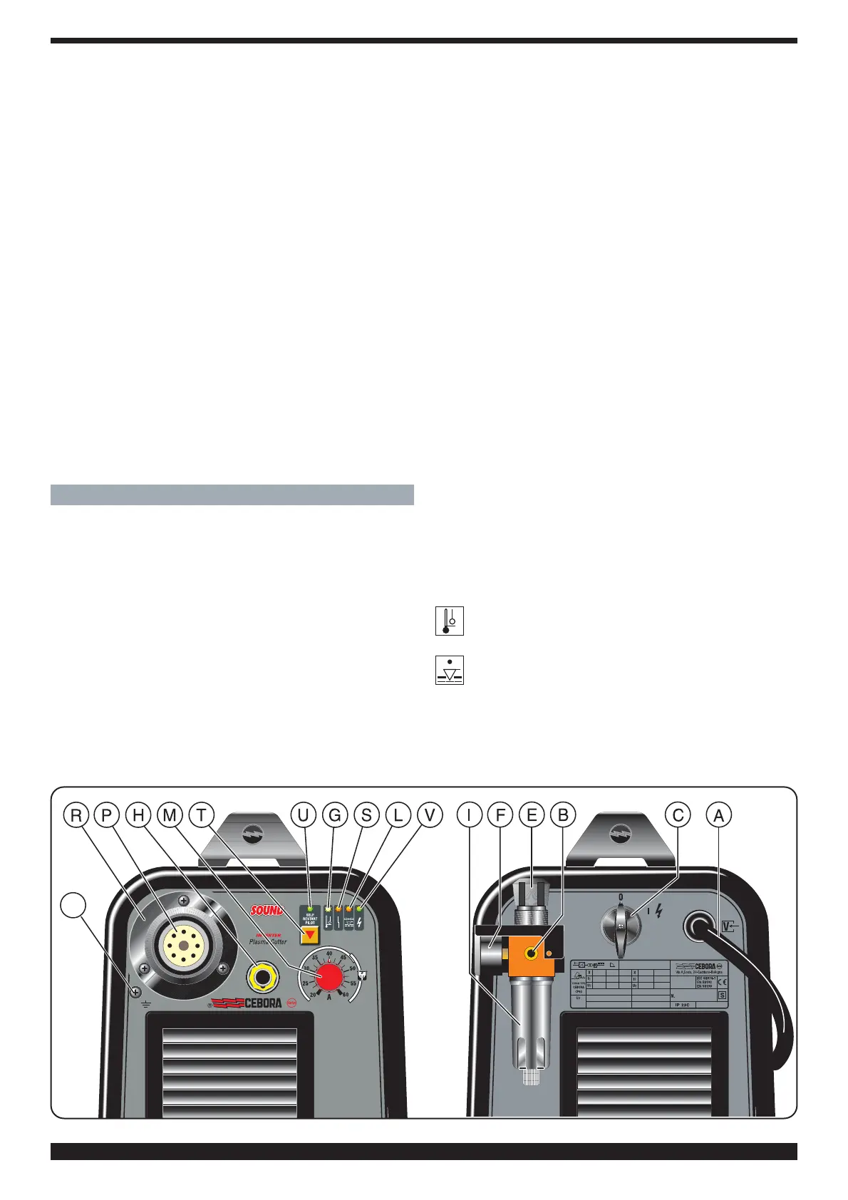
2.2 DESCRIPTION OF DEVICES ON THE MACHINE
A) Power cord
B) Compressed air fitting (1/4" female gas thread)
C) Mains power switch
E) Pressure regulator knob
F) Pressure gauge
G) Thermostat LED
H) Grounding clamp
I) Water trap
L) Low air pressure LED
M) Cutting current regulator knob
P) Torch fitting
R) Safety guard
S) Blocked LED; lights when hazardous conditions
arise.
T) Push-button to activate and deactivate the "SELF-
RESTART PILOT" function.
U) Plasma torch.
V) Mains power led.
W) Earth terminal for straight torches.
2.3 SAFETY DEVICES
This system comes equipped with the following safety
devices:
Overload cutout:
1) To avoid overloads. It is evidenced by the G led
continuosly on (see fig.1).
Pneumatic:
Located on the torch inlet to prevent low air pressu-
re. The LED L lights when tripped (see fig.1).
The blinking L led means that the pressure has tempora-
rily gone below 3.2 ÷ 3.5 bar.
Electrical:
Located on the torch body, to prevent hazardous voltages
from occurring on the torch when, swirl ring, electrode or