7
Alimentazione Feed Speisung Alimentation
Potenza Rating Leistung Puissance
Assorbimento Absorption Verbrauch Absorption
Coppia Torque Kr ftepaar Couple
Rapporto di riduzione Reduction ratio Untersetzungsverh ltnis Rapport de reduction
Classe isolamento Insulation class Isolierklasse Classe d isolement
Interv. termoprotezione Thermoprotection interv. Eingriff Thermorelais Interv. protection thermique
Temp. funzionamento Working. temp. Betriebstemperatur Temper. fonctionnement
Peso max. cancello Feed Tragf higkeit Portee
Velocità apertura Opening speed ffnungsgeschwindigkeit Vitesse d ouverture
Condensatore Condenser Kondensator Condensateur
Lubrificazione Lubrication Schmierung Lubrification
Peso Weight Gewicht Poids
Dimensioni Dimensions Masse Dimensions
V
W
A
Nm
°C
°C
Kg
m/min
µF
Kg
mm
230
Dati tecnici
Alimentación
Potencia
Absorción
Par
Relación de reducción
Clase de aislamiento
Interv. termoprotección
Temp. de funcionamiento
Peso máx. de la cancela
Velocidad de apertura
Condensador
Lubrificación
Peso
Dimensiones
Datos técnicosTechnical data Technische Daten Donnees technique GLISS 500E
280
1,6
36
0,042
F
130
-20°/+70°
500
8,48
16
Olio Agip Blasia 100
13
215x235xH270
Riferimento targhetta sull’azionamento
See operation plate
Siehe Schildchen auf der Motor-Gruppe
Voir la plaque sur le motoréducteur
Referencia tarjeta sobre el accionamiento
135
235
X
F
T
X≈ 50 per cremagliera in Fe 30x12
X≈ 55 per cremagliera in nylon
X≈ 50 for Fe 30x12 rack
X≈ 55 for nylon rack
X≈ 50 para cremallera Fe 30x12
X≈ 55 para cremallera de nylon
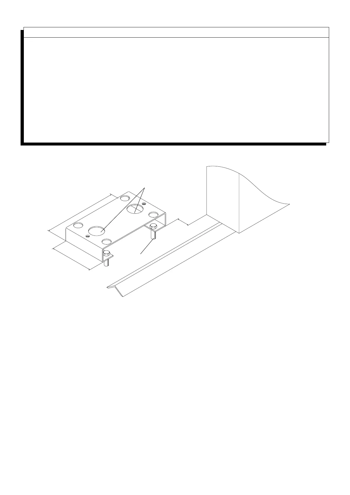
Fig.1
X≈ 50 für Zahnstange aus Stahl 30x12
X≈ 55 für Zahnstange aus Nylon
X
≈
50 pour cremaillére en acier 30x12
X
≈
55 pour cremaillére en nylon
3. Messa in posa della piastra di fondazione
Posizionare a terra la piastra di fondazione seguendo le quote della fig.1, mediante n° 4 tasselli a pressione in
acciaio T (in ogni caso la piastra deve essere perfettamente ancorata a terra).
N.B. Passare sui fori F una guaina adeguata ai cavi di alimentazione dell’attuatore.
3. Foundation slab laying
Secure the foundation slab to the ground with no. 4 steel T pressure inserts to dimensions given in
fig. 1 (it’s important the slab is securely fastened to the ground).
N.b. Go through holes F with a sheath suitable to the actuator feed cables.
3. Montage der Fundamentplatte
Die Fundamentplatte mit 4 Stahl-Spannschrauben am Boden befestigen (siehe Bild Nr. 1).
Anmerkung: ein entsprechender Mantel für die Versorgungskabelkabel des Aktuators durch die Bohrungen F
stechen.
 Loading...