TG0009A
C. E. Niehoff & Co.
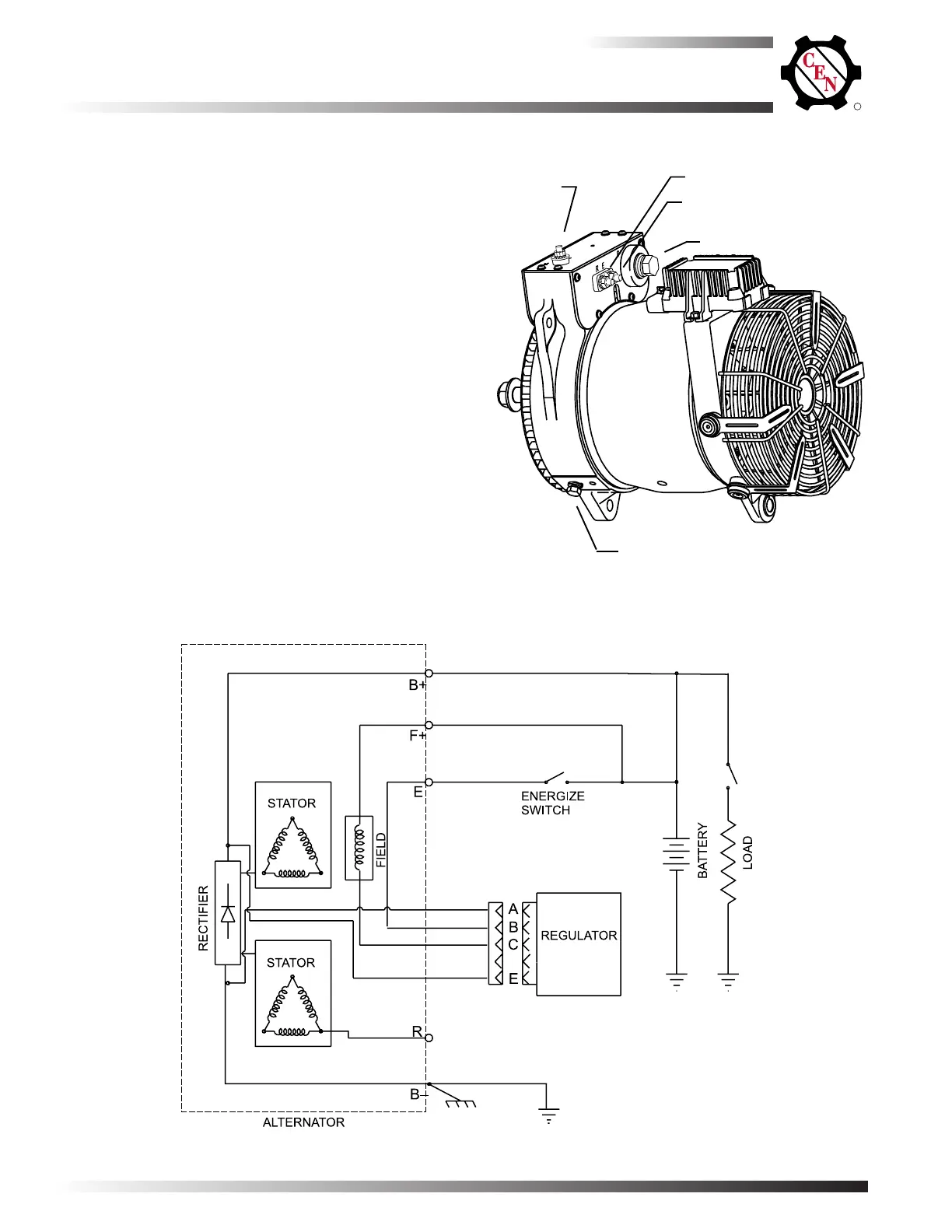
BRUSHLESS ALTERNATORS
The
C711C711
C711C711
C711 alternator (14 V, 360 A)and
C712C712
C712C712
C712 alterna-
tor (14 V, 400 A) are internally rectified. All windings
and current-transmitting components are non-
moving, so there are no brushes or slip rings to wear
out. This unit is externally energized through either
an ignition switch or an energize switch (commonly
an oil pressure switch), which activates regulator.
Field coil is then energized. Regulator maintains
alternator output voltage at regulated setting as
vehicle electrical loads are switched on and off.
Alternator output current is self-limiting and will not
exceed rated capacity of alternator.
A2-121 regulator used with all units has a 15.5 V
regulator setpoint available for battery isolator
applications.
Electromagnetic interference (EMI) is suppressed with
internal filters to acceptable levels defined by the
Society of Automotive Engineers (SAE) specification
J1113/41. A2-121 regulator will not reduce EMI from
sources such as antennas, poor cable routing prac-
tice, or other electronic devices that cause EMI. If EMI
continues, consult an electromagnetic compliance
(EMC) specialist to determine EMI source.
R
Section 1: Wiring Diagram
Page 2
TG9B
 Loading...