R
Page 2
TG97A
Section A: Description and Operation
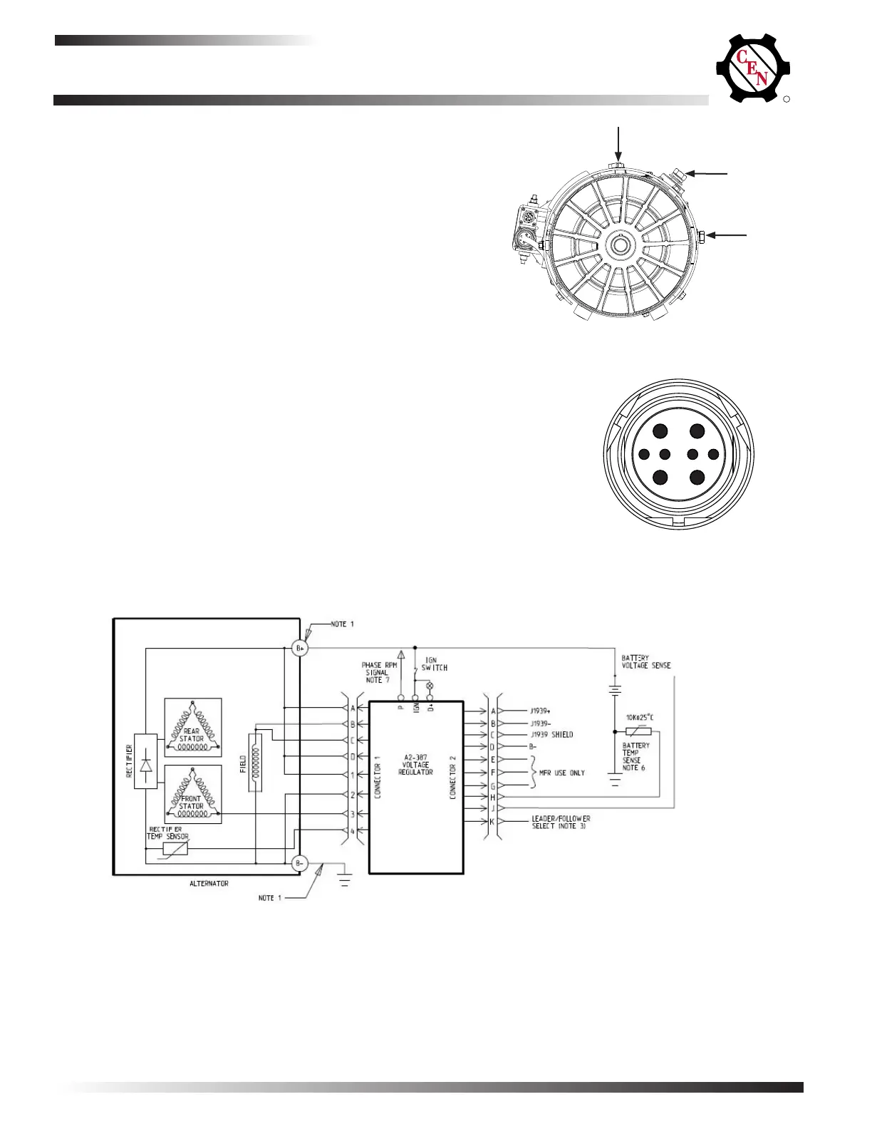
Figure 3: C850 Alternator with Regulator, Wiring Diagram
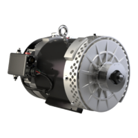
C850 Alternator
Description and Operation
The CEN C850 28 V (550 A) alternator is an internally-
rectied,brushlessalternator.Allwindingsandcurrent-
carrying components are stationary, so there are no
brushes or slip rings to wear out.
Voltage regulator is activated when it receives an igni-
tion/energize signal from vehicle usually via oil pressure
switch or multiplex system. The regulator monitors alter-
natorshaftrotationandprovideseldcurrentonlywhen
it detects the alternator shaft rotating at a suitable speed.
After the regulator detects shaft rotation, it gradually
applieseldcurrent,preventinganabruptmechanical
load on accessory drive system. Soft start may take up to
20 seconds after rotation and energize signals are
sensed.
Refer to Figure 1 for alternator terminal locations. Refer
to Figure 2 for alternator-to-regulator harness plug socket
outputs.
Figure 1: C850 Alternator Terminals
B– terminal
B+ terminal
A D
B C
1
2
3
4
A = B+
B = F1+
C = F2+
D = B+
1 = B+ Sense
2 = B–
3 = Phase (AC)
4 = Temp Sense
Figure 2: Alternator-to-Regulator Harness Plug Socket Outputs
NOTES:
1. Voltage drop at 550 amps between B+ terminal and battery shall not exceed 0.4 Volts. Ground cable should follow the same rule.
2. Connections to terminals “Phase,” “D+,” and to connector 2 are optional
B– terminal
 Loading...