R
Page 5
TG97A
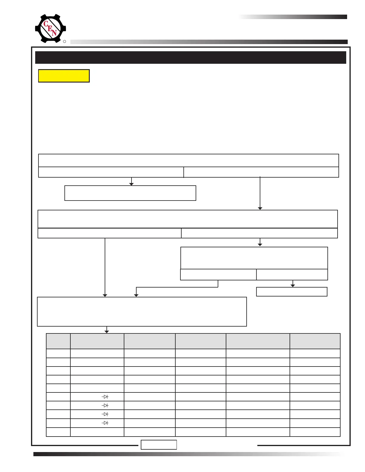
MASTER BATTERY SWITCH OFF, KEY OFF, ENGINE OFF:
Disconnect alternator-to-regulator harness at regulator and perform ALL tests
in table below at harness plug. If ANY expected values are not obtained, unit
indicated in "TESTED CIRCUIT" column is faulty.
Regulator responded to overvoltage condition.
See "Check for OVCO Condition" on page 4.
Shut down vehicle, then restart engine. Wait until system voltages stabilizes. Does alternator function normally?
• TEST MEASUREMENTS ARE TAKEN AT ALTERNATOR HARNESS PLUG. Test measurements from an
extended harness plug may affect results.
• IF AVAILABLE, CONNECT A CEN A10-151 IN-LINE TEST TOOL TO HARNESS PLUG AND CONDUCT
TESTS FROM A10-151 SOCKETS. Otherwise perform all tests directly from harness plug sockets.
• CHECK CONDITION OF FUSES IN REMOTE MOUNTED REGULATOR HARNESS BEFORE TESTING.
• BEFORE TESTING, VERIFY THE FOLLOWING AND REPAIR/REPLACE IF NOT TO SPECIFCATION:
—Batteries for state-of-charge (24.5-28.0 V), condition, and secure connections.
—Master battery switch for function.
TEST
NO.
METER SYMBOL
& SCALE
METER (+) METER (–) TESTED CIRCUIT EXPECTED
VALUE
1 VDC Socket A Socket 2 Regulator B+, B– Battery voltage
2 VDC Socket D Socket 2 Regulator B+, B– Battery voltage
3 VDC Socket 1 Socket 2 Regulator B+, B– Battery voltage
4 Ohms Ω Socket B Socket 2 Alt. Field Coil 1 – 1.5 ohms
5 Ohms Ω Socket C Socket 2 Alt. Field Coil 1 – 1.5 ohms
6
Diode
Socket 3 Socket 2 Alt. AC Blocking
7
Diode
Socket 2 Socket 3 Alt. AC Flow
8
Diode
Socket 3 Sockets A, D, 1 Alt. AC Flow
9
Diode
Sockets A, D, 1 Socket 3 Alt. AC Blocking
10 Ohms Ω Socket 4 Socket 2 Harness/temp sensor 60K-130K ohms
MASTER BATTERY SWITCH ON, KEY ON, ENGINE ON: Test for battery voltage at B+ terminal on alternator
to ground, then at regulator IGN terminal to ground. Does battery voltage exist at both locations?
Yes
No
Repair vehicle wiring as necessary. Run engine and
re-test charging circuit. Is charging system perform-
ing properly?
Yes
No
System is operational
Chart 1: No Alternator Output – Test Charging Circuit
When performing the following steps, make sure probes do not touch other sockets, as
this may create an arc and damage plug.
Yes
No
NOTICE
DO NOT MODIFY THIS CHART
Section C: Advanced Troubleshooting
 Loading...