1. Always check that the circuit breaker in the
electrical panel is in the OFF position, and that
all high voltage circuits (more than 42.4V) are
completely isolated from the mains supply
before doing any work.
2. Ensure that all low voltage systems (less than 42.4V) are
suitably protected from damage, by disconnecting all
sources of power such as chargers and batteries before
doing any work.
3. All electrical work must be carried out according to the
requirements of all applicable local electrical codes. (It is
recommended that a licensed electrical contractor perform
such work).
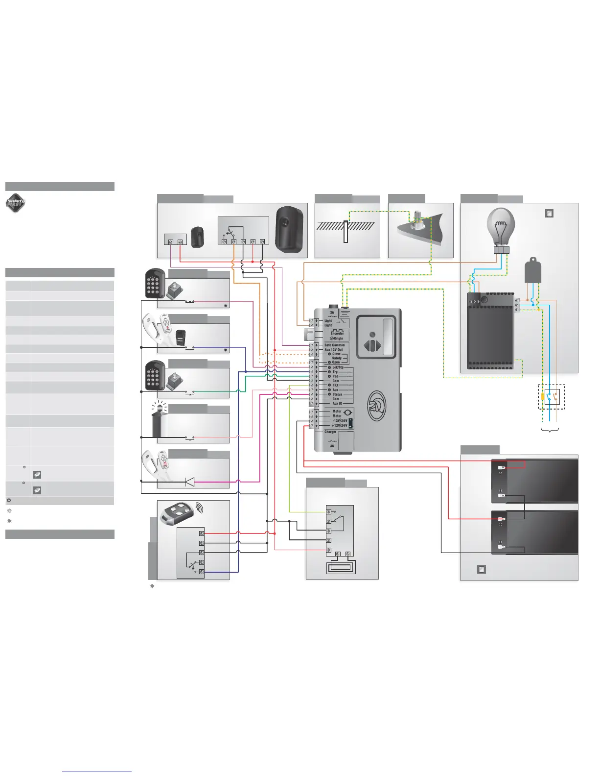
Connect all wiring
Connect the controller to the required input and output devices as per
the wiring diagram on the right hand side.
12V+
12V-
IRB Tx
IRB Receiver
12V+
COM
12V-
NC
NO
Connection type: Normally-closed
Tx
Rx
LNE
L
N
E
Weatherproof
isolator enclosure
within two metres
of motor
LNE
110 - 220V
Mains in
OR
Earth spike
(>1m copper
rod hammered
into the ground)
Holiday lockout
keyswitch/keypad
optional
Connection type: Normally-open
optional
Connection type: Normally-open
Connection type: Normally-open
optional
Connection type: Normally-open
POLOphone
handset status LED
optional
Connection type: Normally-open
optional, but
recommended
Lightning rod
Hold-down
base plate bolt
Pillar Light/
Courtesy Light
POLOphone Intercom
push button
optional
Pedestrian
Keyswitch/Keypad
Pillar light
pushbutton
optional*
External radio
receiver
optional
Loop and Loop
Detector
Battery
Charger
Latched
Non-latched
Loop Detector
Optional 40kA
surge arrestor
12V+
COM
Neg
NC
NO
Radio Receiver
There is an onboard CENTURION receiver.
Switch off the receiver if not being used
Only one 12V battery is used for the D5-Evo
12V+
Neg
COM
NO
NC
L N E
Safety Open Opening beam safety input.
(A normally-closed potential-free input)
Light/Light Pillar light connection.
(A normally-open potential-free input)
Safe Common Used for switching the power supply to the safety
beams, if automatic beam testing is required
Aux 12V Out Auxiliary power connection.
Provides +12V DC supply for auxiliary equipment
such as a radio receiver, photo cells, etc. It is
electronically limited to 300mA
Safety Close Closing beam safety input.
(A normally-closed potential-free input)
Lck/Stp Holiday Lockout or emergency stop input.
(A normally-closed potential-free input)
Trg Trigger input.
(A normally-open potential-free input)
FRX Free-exit input.
(A normally-open potential-free input)
Aux Activates the pillar light relay.
(A normally-open potential-free input)
Ped Pedestrian opening input.
(A normally-open potential-free input)
Com Common termination point.
All trigger signals, etc. have their return path to one
of the Com terminals
Status External gate status indicator.
(A low current output signal). An output terminal
which provides a low current drive (approx. 4,5V
DC, 20mA) to a LED which can be used to indicate
the gate status remotely)
Aux IO The Aux IO terminal provides an open collector
output which can be used for alarm or auto function
purposes
Motor Motor output
D5-Evo - connects to the black motor wire
D10/D10 Turbo - connects to the blue or black
motor wire
12V/24 + Positive battery connection.
12V/24 - Negative battery connection.
Battery terminal normally indicated as + or
red (right hand battery)
Battery terminal normally indicated as - or
black (left hand battery)
12V/24V this will either be 12V or 24V depending on the motor
voltage of the operator
Once the installation has been successfully completed and tested, it is
important for the installer to explain the operation and safety
requirements of the system.
A switch that remains in a connected or
disconnected state similar to a standard light switch
A switch that momentarily makes contact, and may
be spring loaded similar to a push button door step
Latched
Non-Latched
Motor Motor output
D5-Evo - connects to the blue motor wire
D10/D10 Turbo - connects to there orange or red
motor wire
optional
7. Electrical setup
8. Description of terminal functions
9. Installation handover
optional, but
recommended
i5 Infrared safety beams
(opening and closing)
 Loading...