Do you have a question about the Century Helicopter Products Hawk III and is the answer not in the manual?
| Brand | Century Helicopter Products |
|---|---|
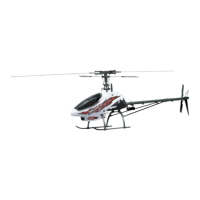
| Model | Hawk III |
| Age Range | 14+ |
| Power Source | Electric |
| Control Type | Radio Control |
| Channels | 4 |
| Engine | Electric Motor |
| Type | Helicopter |
| Material | Plastic |
| Main Rotor Diameter | 22 inches |
| Tail Rotor Diameter | 4 inches |
| Length | 22 inches |
| Height | 6 inches |
Safety warning about the precision of the radio-controlled model.
List of essential items not included in the HAWK III kit.
Tools required for building and setting up the HAWK III helicopter.
Assembling the head block, damper rubbers, and seesaw shaft.
Attaching the offset plate, tie bar, and bearing cups to the rotor head.
Installing balls, slide tube, and bearings into the bell mixer arm.
Installing the feathering shaft, washers, locknut, and pushrods.
Centering and securing the flybar, control arms, and weights.
Attaching balls and mixing arms to the washout hub and swashplate.
Assembling the start shaft guide blocks with bearings and spring.
Installing the collar, start cone, and securing the start shaft.
Assembling the tail rotor output shaft, gear, and bearings.
Installing the drive shaft, counter gear, and alloy drive gear.
Mounting the main gear assembly and auto-rotation bearing to the main shaft.
Attaching the elevator bellcrank, spacers, and balls to the threaded axle.
Installing the mast stopper and side frames onto the main shaft.
Connecting the upper and lower frame assemblies and securing them.
Installing the collective axle, levers, and aileron bellcrank linkage.
Mounting the clutch bell, shoes, fan, and bearings onto the crankshaft.
Securing the engine assembly to the engine mount and installing the throttle extension.
Assembling the fuel tank with tubing, clunk, and caps.
Attaching the fuel tank and lower frames to the gyro plate.
Procedures for balancing the rotor head and attaching main blades.
Adjusting gyro gain, neutral trim, and direction for optimal tail control.
Setting collective pitch values for different flight modes.
Modifying throttle settings for engine run-in and smooth RPM.
Setting gyro gain to prevent tail rotor oscillation or uncontrolled rotation.
Steps for cranking the engine and addressing starting difficulties.