©2016 Cequent™ Performance Products, Inc. - Printed in Mexico Sheet 3 of 18 76112NP 11-10-16 Rev. B
1. Mark centerline appearance panel: Mark centerline of appearance with marker or tape.
2. Remove appearance panel: Remove 5 Philips screw, 9 plastic rivet (Rivets are released by first pulling out center post of rivet, then remove remaining post), 4 plastic screws with large screwdriver (pull
on panel for ease of removal).
3. Lower exhaust: Lower the exhaust by detaching it from the rubber isolator. Spraying a lubricant or soapy water on the metal hanger rod and the rubber isolator helps removal
4. Remove plug and tape: Remove the rubber plugs (1 each side) and if present remove tape covering the weld nuts (3 each side). Run bolts from fastener kit into weld nuts to confirm no interference.
5. Open rear hatch: Open rear hatch on vehicle and remove 2 plastic rivet (1 each side) and 2 small bolt (1 each side).
6. Remove screw from wheel well: Remove (1) Philip screw each side, located inside fascia at the lower attaching points between rear fascia and rear side panel of vehicle.
7. Remove lower rear fascia: Gently pull up from the rear wheel well panel each side, unclipping the tabs inside , while working around to rear. If present disconnect any wiring harness at the fascia, and
put the fascia cover aside.
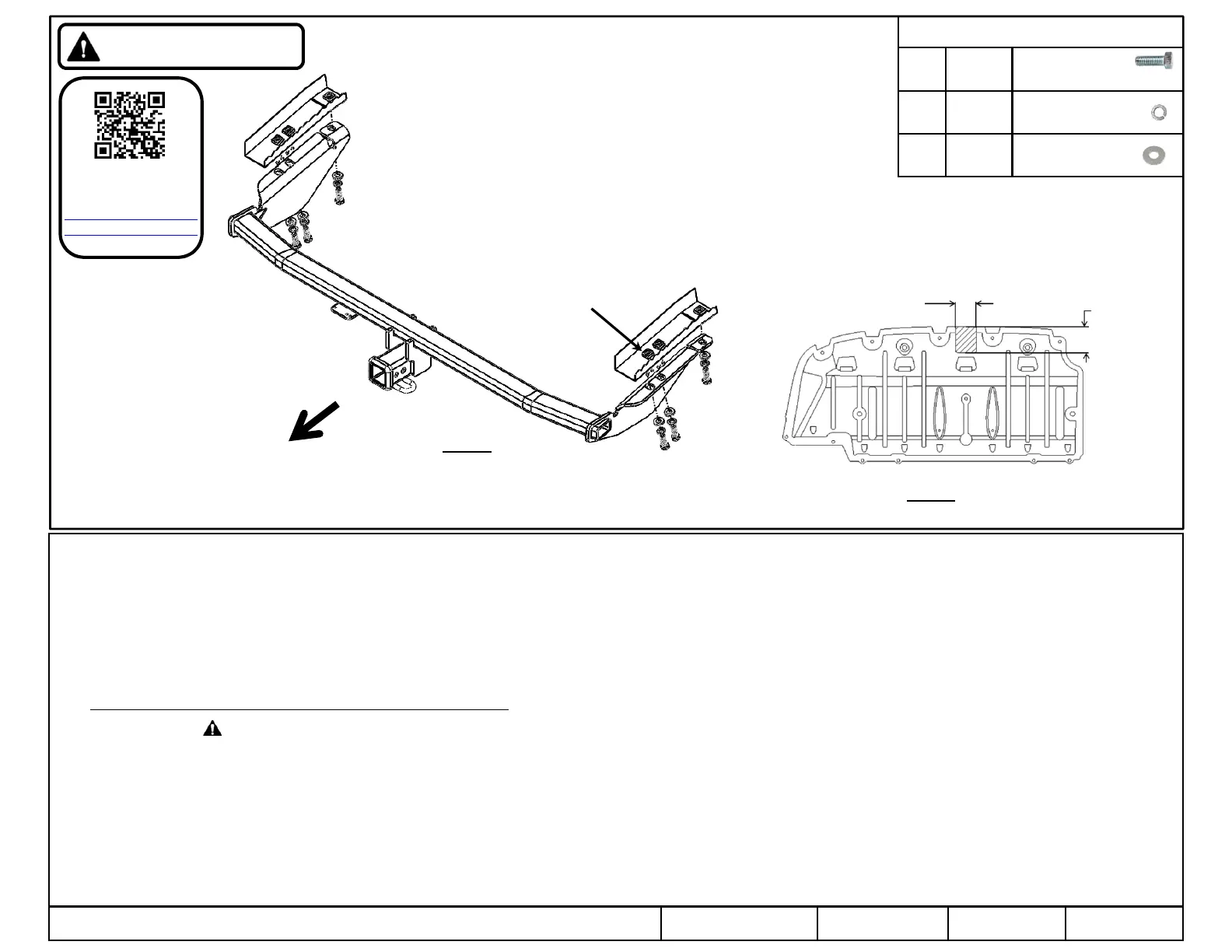
8. Raise hitch: Raise hitch into position and install hex bolts, lock washers and flat washers into existing weldnuts in frame, as shown above. Push hitch toward driver’s side and tighten fasteners.
9. Tighten all M812 CL10.9 fasteners with torque wrench to 75 Lb.-Ft. (102 N*M)
10. Reattach exhaust: Raise exhaust back into position and reattach to the rubber isolator.
11. Reinstall fascia: Reinstall fascia: starting from the center of the vehicle lineup and gently reinstall the rear fascia and all fasteners in reverse order. (Note: reattach any wiring hardness if removed)
12. Trim appearance panel: Appearance panel will need to be trimmed or not reinstalled. Obtain owner permission before trimming. Trim appearance panel as shown. See figure 2. Reinstall if trimmed.
Note: check hitch frequently, making sure all fasteners and ball are properly tightened. If hitch is removed, plug all holes in trunk pan or other body panels to prevent entry of water and exhaust fumes. A hitch or
ball which has been damaged should be removed and replaced. Observe safety precautions when working beneath a vehicle and wear eye protection. Do not cut access or attachment holes with a torch.
This product complies with safety specifications and requirements for connecting devices and towing systems of the state of New York, V.E.S.C. Regulation V-5 and SAE J684.
Figure 2
Fastener Kit : 76112F
① Qty. (6) Hex bolt
M12 X 1.25 X 40mm CL10.9
② Qty. (6) Lock washer
1/2”
③ Qty. (6) Flat washer
1/2”
Rear
Figure 1
Installation Instructions
PART NUMBERS: 76112, 84112, CQT76112
Proper torque is needed to keep the hitch secure to the vehicle when towing.
Always wear SAFETY GLASSES
when installing hitch
①
②
③
Note: Fasteners typical
both sides
Existing
weldnuts
5.00
[127. mm]
4.00 [101.6 mm]
Scan for step by step
PHOTO installation
instruction or visit
http://www.cequentgro
up.com/qr-product.aspx
 Loading...