Do you have a question about the Ceragon Fibe-Air IP-10G and is the answer not in the manual?
| Brand | Ceragon |
|---|---|
| Model | Fibe-Air IP-10G |
| Category | Network Hardware |
| Language | English |
Covers essential safety measures for operating and handling equipment, including radiation and electrical hazards.
Details how the equipment is packed at the factory with moisture-absorbing bags.
Guidelines for keeping the equipment dry and secure during transportation according to standards.
Procedure to check packing lists for correct part numbers and quantities of components.
Instructions for unpacking and checking the delivered equipment for damage or missing parts.
Lists necessary tools for mounting the IDU, including screwdrivers and crimping tools.
References sections detailing interface connectors and their pin-outs for IDU installation.
Details specific electrical codes and safety requirements for installation in North America.
Outlines environmental, accessibility, and power requirements for the installation site.
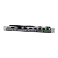
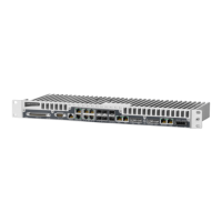
Shows the physical dimensions of the FibeAir IP-10 IDU in millimeters.
Explains standalone and nodal configuration options for the IP-10 system.
Procedure for mounting the IDU into a standard 19-inch or ETSI rack.
Instructions for installing the IDU into a nodal enclosure for nodal configurations.
Describes main and extension nodal enclosures and their backplane interfaces.
Lists the required kits needed to install an IDU in a nodal configuration.
Step-by-step guide for installing IDUs within nodal enclosures.
Details proper grounding methods and electrical connection requirements for the IDU.
Explains the dual DC inputs for power redundancy and their indicator LEDs.
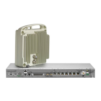
A table to assist in selecting the appropriate RFU based on various technical characteristics.
Instructions for connecting coaxial cables between the IDU and RFU, including sealing procedures.
Steps to establish an initial network connection to the IDU for configuration.
Guide on accessing and using the Web-Based Element Management System for configuration.
Procedure for setting local and floating IP addresses for the IDU.
Instructions for downloading and preparing for IDU software upgrades.
How to check the current software versions installed on the IDU.
Steps for downloading software packages via FTP for IDU upgrades.
Detailed procedure for performing software upgrades on the IDU.
Process for entering and activating a license key to enable features.
Explanation of Cross Polarization Interference Canceller (XPIC) feature and its setup.
Prerequisites and conditions necessary for enabling the XPIC feature.
Steps to configure antennas and RFUs specifically for XPIC operation.
Methods to view the Cross Polarization Interference (XPI) values via Web EMS or CLI.
Checklist for verifying site installation requirements and safety.
Provides additional details and clarification for items in the site acceptance checklist.
Tests and verification steps for a 1+0 radio link configuration.
Tests and verification steps for a 1+1 HSB radio link configuration.
Tests and verification steps for a 2+0 XPIC radio link configuration.
Document for recording all commission details and test results for the installed link.
Description of Gigabit Ethernet interfaces for main data transmission.
Details of the wayside channel interface for auxiliary audio or data.
Description of the protection channel interface for redundancy.
Details of the out-of-band management channel interface.
Specifications for the order wire channel used for audio transmission.
Information on the user channel interface for audio transmission.
Pin assignment details for the 9-pin external alarms D-type connector.
Pinout for the RJ-45 connector used for protection, wayside, and management.
Pinout information for the IDU power connector.
Pinout details for the 68-pin SCSI connector for E1/DS1 interfaces.
Pin assignment for the RJ-45 connector used for Gigabit and Fast Ethernet.
Pinout for the RJ-45 connector used for 10/100 Ethernet.
Pin assignment for the RJ-45 user channel connector.
Pinout details for the 9-pin RS-232 craft terminal connector.
Step-by-step guide for replacing the fan tray in the IDU unit.