Do you have a question about the Ceriotti VISION and is the answer not in the manual?
Indicator light showing the operational status of the hairdryer unit.
Control for setting the operating duration of the hairdryer.
Adjusts the airflow speed of the hairdryer.
Regulates the temperature output of the hairdryer.
Indicates a potential issue with the power supply connection.
Audible indicator, likely for timer or function completion.
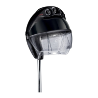
Protective screen or shield for the user's face.
The main housing or dome of the hairdryer.
The edge or rim of the hairdryer hood.
A component for supporting or positioning the hairdryer arm.
Verify model details on the label and match power specs to the mains supply.
Ensure the appliance is disconnected from power before mounting or dismounting.
Company disclaims liability for injury from unsuitable wall support materials.
Use a damp cloth with mild detergents; disconnect and cool before cleaning.
Do not use near water; keep away from bath/shower users; disconnect after use.
Contact manufacturer or service center for internal parts or power cord issues.
Advised to install a differential power unit (30mA) for additional protection.
Guidelines for children's use, including age limits and supervision requirements.
Ensure proper air intake by not blocking the top grill for correct operation.
Company not liable for damage from non-authorized installation or non-OEM parts.
Instructions on how to tighten a loose articulated hood joint using an Allen wrench.
Procedure to tighten a loose front flap by adjusting lateral stoppers.
Setting the timer from 0-60 minutes; knob C also acts as a main switch.
Setting desired temperature via knob E; warning light (B) indicates heating.
Setting timer 0-60 mins; knob C doubles as main switch.
Setting temperature via knob E; warning light (B) shows heating progress.
Adjusting ventilation speed using knob D (1-2).
Setting timer 0-60 mins; knob C doubles as main switch.
Setting temperature via knob E; warning light (B) shows heating progress.
Adjusting ventilation speed via knob D (1-4 for different speeds).
Setting timer 0-60 mins; knob C doubles as main switch.
Setting temperature via knob E; warning light (B) shows heating progress.
Adjusting ventilation speed via knob D (1-6) for varied applications.
Steps for assembling the central base, supporting pole, and small pedestal.
Steps for mounting the bracket, plate, and arm onto the wall.
How to adjust the arm's counterweight screw (G) for proper balance.
Instructions for disposing of the device separately for recycling.
Guidelines for safe cleaning: disconnect, avoid water immersion, use mild agents.
Warranty valid for 12 months; covers manufacturing or material flaws.
Excludes damage from misuse, tampering, accident, or transport.
Repairs by manufacturer only; shipping costs are buyer's responsibility.
Enclose filled warranty certificate and fiscal receipt for claims.
| Brand | Ceriotti |
|---|---|
| Model | VISION |
| Category | Hair Dryer |
| Language | English |