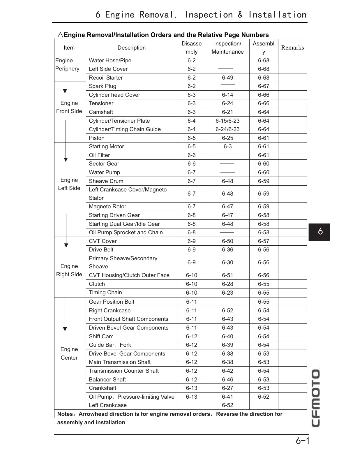
Engine Removal/Installation Orders and the Relative Page Numbers
Item Description
Disasse
mbly
Inspection/
Maintenance
Assembl
y
Remarks
Water Hose/Pipe 6-2 6-68
Left Side Cover 6-2 6-68
Engine
Periphery
Recoil Starter 6-2 6-49 6-68
Spark Plug 6-2 6-67
Cylinder head Cover 6-3 6-14 6-66
Tensioner 6-3 6-24 6-66
Camshaft 6-3 6-21 6-64
Cylinder/Tensioner Plate 6-4 6-15/6-23 6-64
Cylinder/Timing Chain Guide 6-4 6-24/6-23 6-64
Engine
Front Side
Piston 6-5 6-25 6-61
Starting Motor 6-5 6-3 6-61
Oil Filter 6-6 6-61
Sector Gear 6-6 6-60
Water Pump 6-7 6-60
Sheave Drum 6-7 6-48 6-59
Left Crankcase Cover/Magneto
Stator
6-7 6-48 6-59
Magneto Rotor 6-7 6-47 6-59
Starting Driven Gear 6-8 6-47 6-58
Starting Dual Gear/Idle Gear 6-8 6-48 6-58
Engine
Left Side
Oil Pump Sprocket and Chain 6-8 6-58
CVT Cover 6-9 6-50 6-57
Drive Belt 6-9 6-36 6-56
Primary Sheave/Secondary
Sheave
6-9 6-30 6-56
CVT Housing/Clutch Outer Face 6-10 6-51 6-56
Clutch 6-10 6-28 6-55
Engine
Right Side
Timing Chain
6-10 6-23 6-55
Gear Position Bolt 6-11 6-55
Right Crankcase 6-11 6-52 6-54
Front Output Shaft Components 6-11 6-43 6-54
Driven Bevel Gear Components 6-11 6-43 6-54
Shift Cam 6-12 6-40 6-54
Guide BarFork
6-12 6-39 6-54
Drive Bevel Gear Components 6-12 6-38 6-53
Main Transmission Shaft 6-12 6-38 6-53
Transmission Counter Shaft 6-12 6-42 6-54
Balancer Shaft 6-12 6-46 6-53
Crankshaft 6-13 6-27 6-53
Oil PumpPressure-limiting Valve
6-13 6-41 6-52
Engine
Center
Left Crankcase 6-52
Notes









 To Next Page