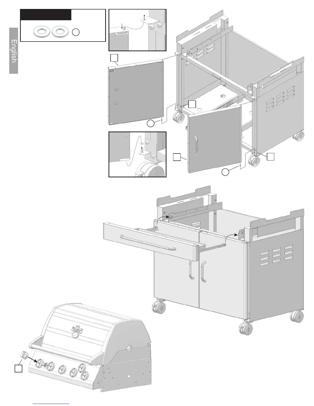
Figure L:
Step 21: Place the drawer assembly (from
step18) into the drawer tracks.
Figure M:
Step 22: Install six control knobs (26) onto the
control panel by pushing them on to the valve
stems as shown.
HARDWARE:
Nylon
Washer
K
K
K
53
56
55
52
Figure K
Figure L
Figure K:
Step 19:
Step 20:
Place the nylon
washers (K) onto the lower
door mounts (52 & 55).
Mount the doors
(53 & 56) to the lower door
mounts (52 & 55).
The holes in the doors slide over
the lower door mount hinges
(see Figure K1).
The pins in the top of the doors
are spring-loaded - push the
pins in and snap them into the
upper door hinge tab. (see
Figure K2)
Note: doors can be adjusted by
loosening and adjusting the
lower door mount hinges
(52&55) as necessary.
Right
Left
Figure K2
Figure K1
14
Figure M
26