17
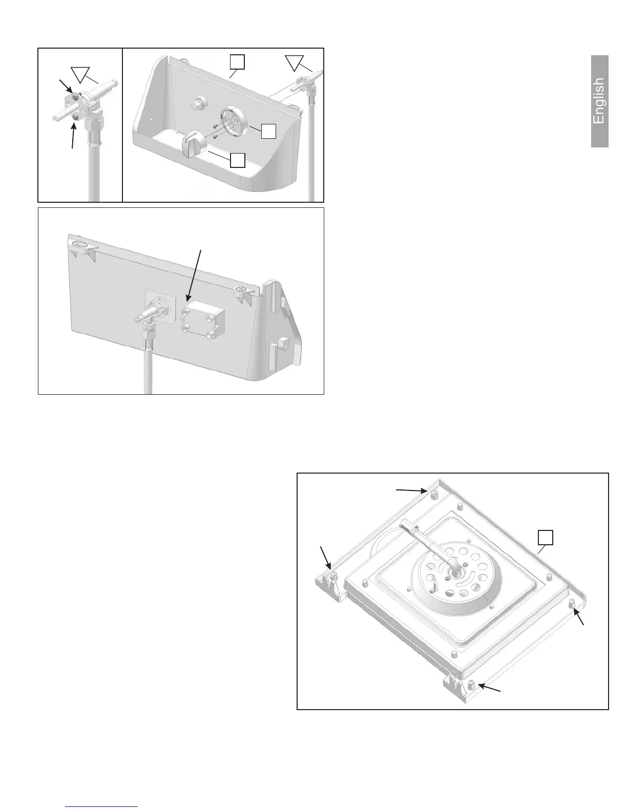
Figure S1, S2 & S3:
Step 30: Remove the two screws (A) from the
side burner valve (b) indicated as shown. Do
not discard the screws - they will be used in
the next step.
Step 31: Attach the side burner valve (b) and
knob bezel (25) to the right side condiment tray
(32) as shown. Use the two screws previously
removed in step 28 to secure the valve and bezel
to the tray.
Securely tighten the screws then push the burner
knob (26) onto the valve.
Following step 30, the back of the right-side
condiment tray should look as shown in figure S3.
Note: The terminal posts on the igniter must be
oriented closest to the valve.
Figure S2
Figure S3
32
25
26
b
Back
Terminal Posts
Figure
S1
A
A
b
Figure T:
Step 32: Remove the four screws (B) from
the side burner table (31) indicated as
shown. Do not discard the screws - they will
be used in the next step.
Figure T
31
B
B
B
B