1
The hood MUST be installed on the sensor BEFORE mounting.
BEST PRACTICES FOR INSTALLING AND
ALIGNING PHOTOELECTRIC SENSORS
(MODELS LMRRU AND LMTBU)
Lock washer
(sharp side up)
Retaining nut
Screw
Hood
Hood
Screw
Reflector
Cut excess
Center hole
Curved slots
Reflector
Line level
Blue LED
Sensor
Line level
Blue LED
Receiver
Blue LED
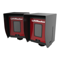
RETR0-REFLECTIVE SENSOR - LMRRU
THROUGH BEAM SENSOR - LMTBU
Sweet spot
Emitter
Sweet spot
To see a video of these instructions, visit:
LiftMaster.com/ul325gates and click on the link under
“View Videos” or search YouTube for LiftMaster
phototelectric sensors.
Refer to the manuals for complete installation instructions.
This addendum will show best practices for installing and aligning the retro-
reflective (LMRRU) and through beam (LMTBU) photoelectric sensors. The
intensity of the emitter beam is highest toward the center and weakest toward the
outer edge. Centering the alignment in the “sweet spot” reduces nuisance
interruptions caused by environmental factors.
• There MUST be a clear line of site from the emitter to the reflector or
receiver.
• Mount the bottom edge of sensors no higher than 24.5" (62.2 cm) above
ground level and with the edge of the sensor and reflector no farther than
3.5" (9 cm) from the vertical plane of the gate.
• Do NOT mount the brackets to surfaces that vibrate or are unstable.
• Do NOT permanently weld or screw brackets into position until AFTER
alignment is complete.
RETRO-REFLECTIVE SENSOR - LMRRU
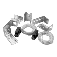
1. Attach the sensor bracket with the screws provided. Tighten the screw in
the center hole but leave the screw in the curved slot loose.
2. Level the bracket with a bubble level.
3. Tighten the screw in the curved slot to secure the bracket.
4. Use a line level to locate the height for the reflector bracket. Mark the
height.
5. Attach the reflector bracket just above the mark with the hardware provided.
6. With the gate closed measure 3.5" (9 cm) from gate to determine which
holes to use to attach the reflector.
7. Attach the reflector and hood to the bracket with the hardware provided.
8. Assemble the sensor with hood to the bracket using the hardware provided:
a. Place the sharp side of the lock washer towards the bracket.
b. Loosely hand tighten the retaining nut.
9. Wire the sensor to the gate operator and make sure the operator is
powered. See the manual for wiring instructions. The blue LED will light to
indicate alignment.
10. Turn the sensor to the left until the red LED lights, indicating misalignment.
Turn the sensor to the right until the red LED lights. Align the sensor in the
middle until the blue LED lights. This is the “sweet spot” for optimal
performance.
11. Hand tighten the retaining nut and then use an adjustable wrench to turn an
additional 1/2 turn. Do NOT over-tighten.
12. You may cut off the unused part of the reflector bracket.
13. Secure conduit to the sensor using watertight fittings (not included). Make
sure to connect the conduit to the inner threads of the sensor.
THROUGH BEAM SENSORS - LMTBU
1. Attach the EMITTER bracket with the screws provided. Tighten the screw in
the center hole but leave the screw in the curved slot loose.
2. Level the bracket with a bubble level.
3. Tighten the screw in the curved slot to secure the bracket.
4. Clamp the RECEIVER bracket at the approximate mounting location.
5. Tie a line level between the brackets and adjust the height of the RECEIVER
bracket until it is level with the EMITTER bracket.
6. Attach the RECEIVER bracket with screws, level the bracket, and tighten the
screws.
7. Assemble the EMITTER with hood to the bracket using the hardware
provided:
a. Place the sharp side of the lock washer towards the bracket.
b. Hand tighten the nut first and then use an adjustable wrench to turn
an additional 1/2 turn. Do NOT over-tighten.
8. Wire the EMITTER to the gate operator and make sure the operator is
powered. See the manual for wiring instructions. The blue LED will light to
indicate power.
9. Assemble the RECEIVER with hood to the bracket. Loosely hand tighten the
nut. Wire to the operator. The blue LED will light to indicate alignment.
10. Turn the RECEIVER to left until the red LED lights, indicating misalignment.
Turn the RECEIVER to the right until the red LED lights. Align the RECEIVER
in the middle until the blue LED lights. This is the “sweet spot” for optimal
performance.
11. Hand tighten the nut on the sensor and then use an adjustable wrench to
turn an additional 1/2 turn. Do NOT over-tighten.
12. Secure conduit to the sensor using watertight fittings (not included). Make
sure to connect the conduit to the inner threads of the sensor.
It is strongly recommended that you test the gate operator to ensure that
vibrations and gate movement do not cause changes in alignment BEFORE
welding or making any permanent connections.
All LiftMaster Training and Troubleshooting videos can be
found by visiting LiftMaster.com/ul325gates or on YouTube.