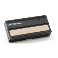
© 2000, The Chamberlain Group, Inc.
01-16702C All Rights Reserved
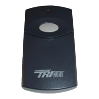
TC1
Single Channel Transmitter
TC2
Dual Channel Transmitter
Step 4 Test the Equipment
If not already installed, connect the receiver to the
operator as described in their installation instructions.
Be sure the door/gate area is clear of people and
obstructions. Activate the transmitter button to verify
that the receiver Relay “clicks” & the opener activates.
If the receiver relay does not “click” verify power
connection to receiver. Then review configuration & DIP
switch settings in both devises.
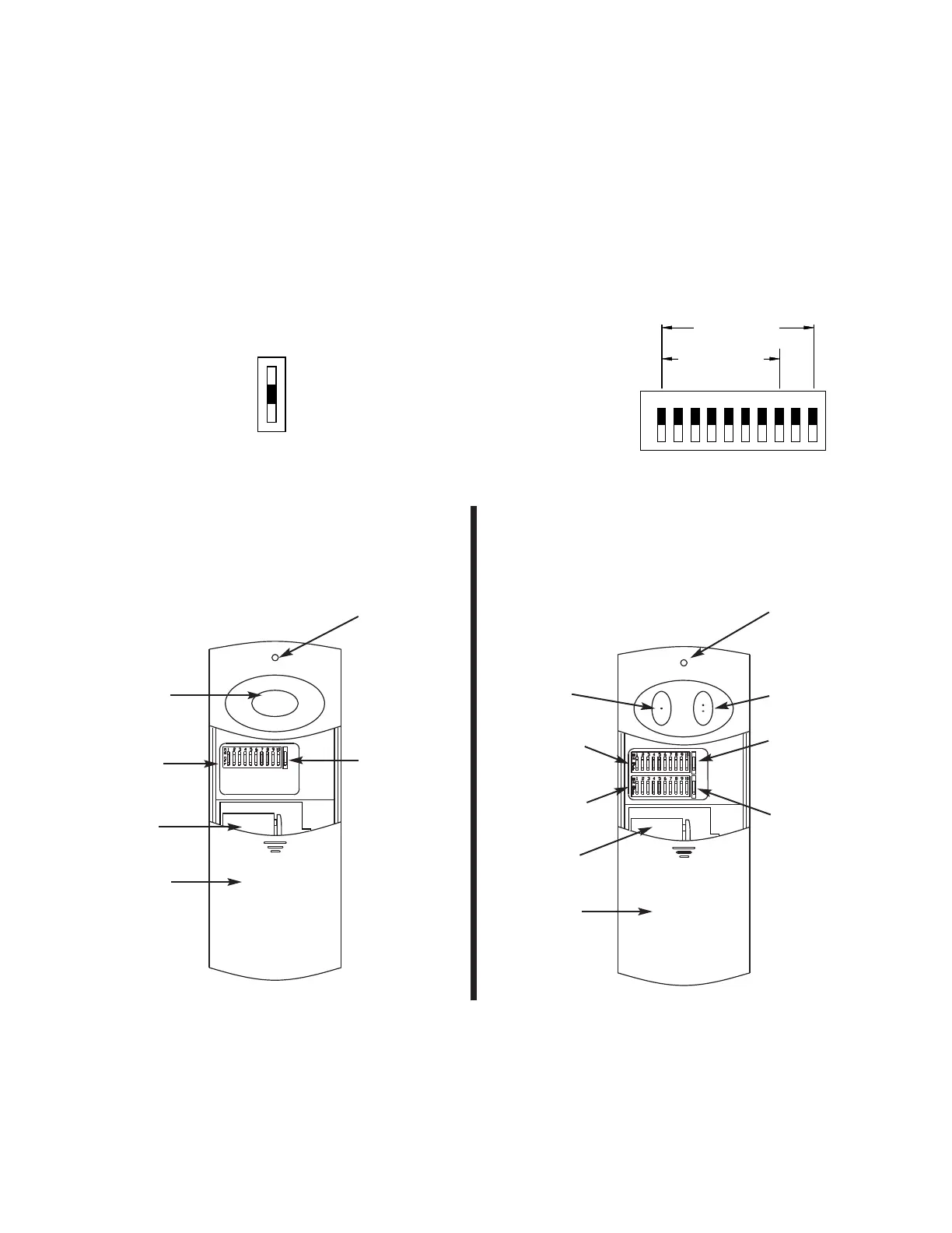
Push Button
DIP Switch
Battery 9V
Sliding Cover
Configuration
Switch
FIGURE 3
Left Button
DIP Switch 1
(Left Button)
DIP Switch 2
(Right Button)
Battery 9V
Sliding Cover
Right Button
Configuration
Switch 1
(Left Button)
Configuration
Switch 2
(Right Button)
INSTALLATION AND SERVICE INFORMATION ARE AVAILABLE
6 DAYS A WEEK CALL OUR TOLL FREE NUMBER
1-800-528-3536
HOURS 7:00 TO 3:30 p.m. (Mountain Std. Time)
MONDAY Through SATURDAY
OR CONTACT US THROUGH THE WEB AT
WWW. CHAMBERLAINGROUP.COM
FIGURE 4
Battery Check
LED
Battery Check
LED
If receiver “clicks” but opener doesn’t activate, review
connection between receiver & opener verifing relay out
to the matching relay in (See figure 4).
Battery Replacement
The 9 volt battery should last 12 to 18 months of normal
use. The green LED on the face of the transmitter will
light dimly or not at all when the battery needs replacing.
The battery is located under the access cover.
FIGURE 1
 Loading...