Installation
COLD
WATER
A drain water tempering eld installation kit P/N 1117084 is included with the machine.
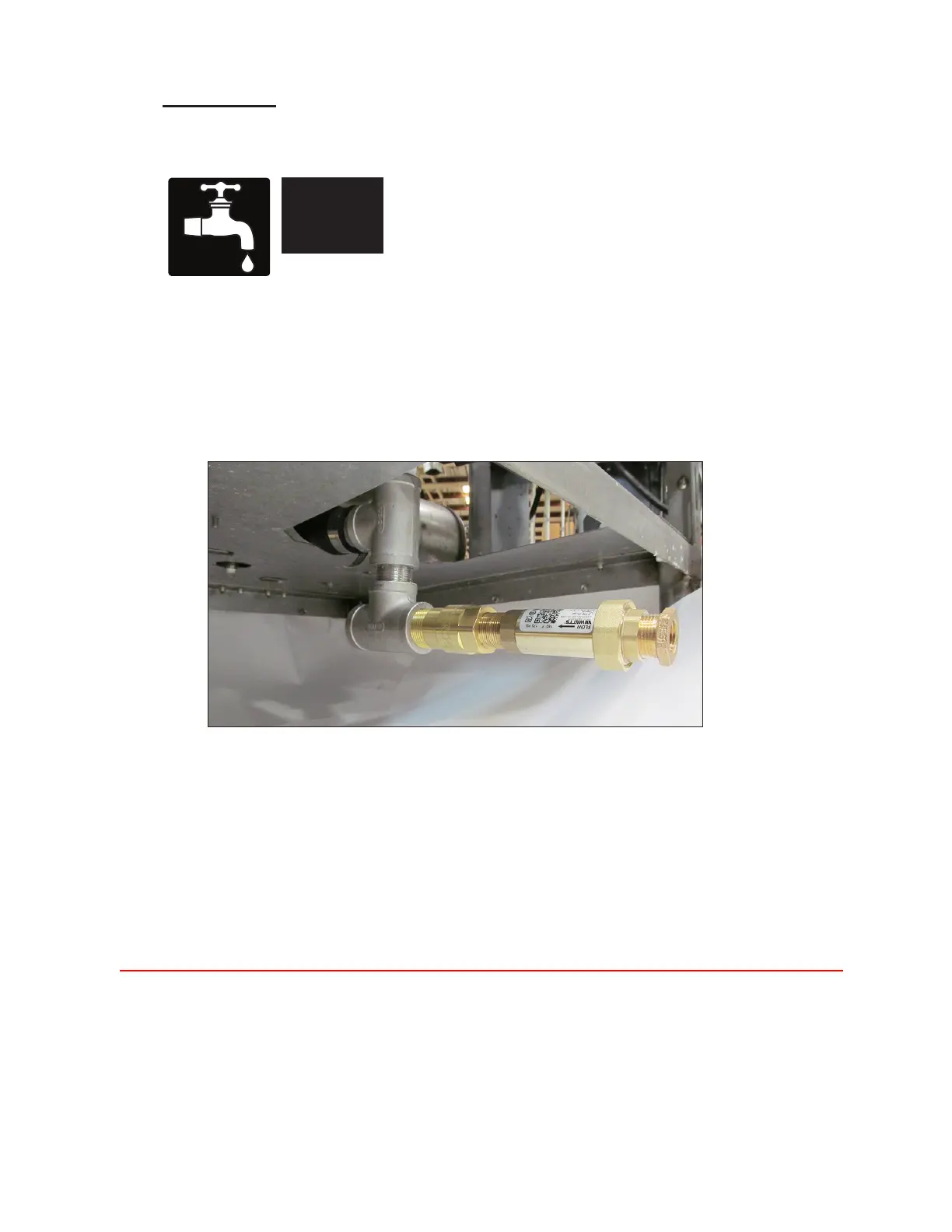
Fig. 8 - Mechanical drain water tempering valve
Installing the kit:
1. Installations should be done by a plumber in accordance with local plumbing codes.
2. Turn water and power o to the machine.
3. Remove panels.
4. Do not use sweat connections on any part of the kit to avoid damage to the tempering valve.
5. Connect the tempering valve to the drain line as close to the hot water discharge as possible.
6. Connect a 1/2" NPT cold water line to the tempering valve.
7. The installation of a ball shut-o valve for servicing (supplied by others) is highly recommended.
8. Maintain an indirect (air gap) connection to the oor drain, if the exit of the Tee is nished to
the oor drain.
9. Restore water supply and check for leaks.
10. Restore power and test the operation of the machine.
11. Replace panels.
12. Installation is complete.
Optional Mechanical Drain Water Tempering Valve Kit
Minimum/Maximum Incoming
Temperature
55-75º/13-24ºC
Minimum Incoming Supply
Flowing Pressure
46-50 PSI
Minimum/Maximum Operating
Flowing Pressure
16 PSI
• Water hardness of 3 Grains/US Gal. - 0.83 Imp. Gal - 5.3 mg/L or less.
7
Mechanical Water Valve
Requires a minimum 1/2" NPT cold water supply line.
Uses building water supply pressure.
 Loading...