Trouble Shooting
Hum in stereo channel: If, at any time, there is a noticable hum associat-
ed with the stereo channel and the power Y adapter is being used, put the
5601 on its own power supply.
Audio Does Not Sound Correct: Make sure the the DIP switches on the
side of the of the 5601 are set according to the chart. If your modulator is
not included in the chart check the ChannelPlus web site for current
updates and a listing of modulators that are unable to function with
the 5601. www.channelplus.com
power
AUDIO
L
AUDIO
R
VIDEO
OUTPUT
LOOP
1 2 3 4 5 6 7 8 9 10
CableVision
®
V101
ChannelVision
®
CVT series
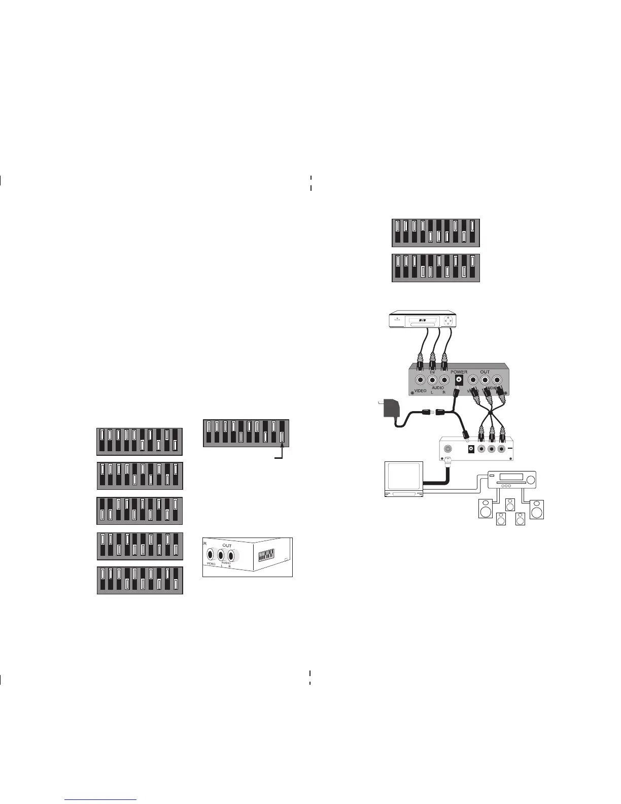
5601 stereo
convertor
Audio source
Video and
audio outs
TV with audio
out to A/V
receiver
A/V receiver
with stereo
speakers and
optional sur-
round sound
speakers
Supplied loop thru
cable to existing
modulator
Y power
adapter
Connecting the 5601
1 2 3 4 5 6 7 8 9 10
Net Media
®
MM70 series
PRINTER’S INSTRUCTIONS:
MANUAL 5601 STEREO CONVERTER - LINEAR P/N: 600-133 C - INK: BLACK - MATERIAL: 20# MEAD BOND - SIZE: 8.500” X 11.000” - FOLDING: 1 FOLD VERTICAL - SCALE: 1-1 - SIDE 2 OF 2
The ChannelPlus model 5601 stereo converter encodes the left and right
baseband audio channels from a stereo source, into the BTSC stereo multi-
plex format required for NTSC modulators. Putting this product in front of a
normally monaural modulator allows it to transmit the audio signal, maintain-
ing the original MTS stereo and surround sound information. DIP switches
are used to set the correct pre-emphasis and modulation level for each
listed modulator.
Contents:
5601 stereo converter
Power supply, 15VDC 300mA
Power plug Y adapter
Coax loop thru cable, 2 feet
Controls & Connections
The unit consists of three baseband video and audio inputs that connect to
the stereo source (IN). The three video and audio outputs (OUT) connect to
the modulator.
Power is supplied from the 15VDC power cube. The 5601 consumes approx-
imately 1 watt of power. Assuming this will not load down the existing modu-
lators power supply, the 5601 may be powered by using the included power
Y adapter. The 5601 will also run off the 12VAC power cube used with the
ChannelPlus 5200 series, 3024 and 3026 ALL-In-One modulators.
DIP Switch Settings
The 5601 must be set for the type of modulator it will be connected with to
ensure proper stereo sound. Using the list, set the DIP switches on the 5601
to the setting for your modulator.
ChannelPlus
5400 series
(no termination)
ChannelPlus
3024, 25, 26,
Radio Shack
®
15-1238 ch 3
ChannelPlus
5214 & 5216
1 2 3 4 5 6 7 8 9 10
1 2 3 4 5 6 7 8 9 10
1 2 3 4 5 6 7 8 9 10
1 2 3 4 5 6 7 8 9 10
DIP switches
located on side
of 5601
1 2 3 4 5 6 7 8 9 10
NOTE:
White area
indicates
switch
position
ChannelPlus
A and D series
1 2 3 4 5 6 7 8 9 10
 Loading...