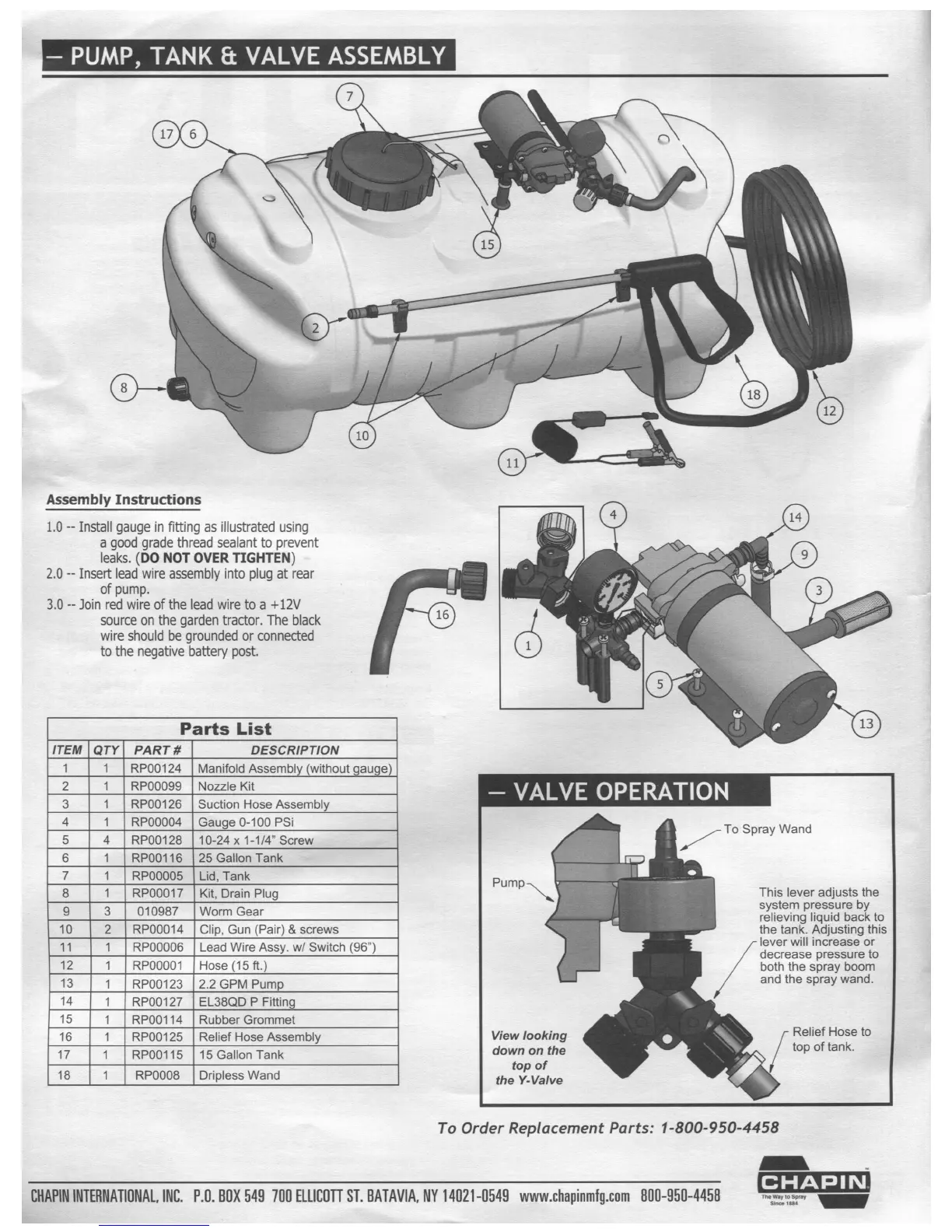
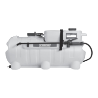
— PUMP, TANK
& VALVE ASSEMBLY
Q
Assembly Instructions
1.0 —- Install gauge
in tting as illustrated
using
a good grade thread sealant to prevent
leaks. (D0 NOT OVER TIGHTEN)
2.0
-- Insert lead wire assembly into plug at
rear
of pump.
3.0 -- Join red wire of the lead wire to a +12V
source on the garden tractor. The black
wire should be grounded o_r connected
to the negative battery post.
\\
(:3
Parts
List
ITEM
QTY
PART#
DESCRIPTION
_;
.4
RPO0124 Manifold Assembly
(without gauge)
l\J
_>
RPO0O99
Nozzle Kit
(D
_\
RP00126
Suction Hose Assembly
-l>
_\
RPOOOO4
Gauge 0-100 PSi
U1
A
RP00128 10-24
x 1-1/4" Screw
O3
._\
RP00116 25 Gallon Tank
\|
_\
RP000O5
Lid, Tank
(Xi
_x
P
RPOOO17
Kit, Drain Plug ump\
(O
£0
010987 Worm Gear
._\
Q
IQ
RPOOO14 Clip, Gun (Pair) & screws
_\
_;
_\
RPOO006 Lead Wire Assy. w/ Switch (96")
.¢
l\)
_|.
RPOOOO1 Hose (15
ft.)
_\
(D
._\
RPO0123 2.2 GPM Pump
_\
-B
_\
RPOO127
EL38QD P Fitting
_\
U1
_\
RP00114 Rubber Grommet
_;
O’)
_\
RP00125 Relief Hose Assembly View l00Ki"9
_\
*1
_\
RP00115 15 Gallon Tank d°W" °" the
_\
®
_\
top of
RPOOO8 Drlpless Wand the Y4/awe
To
Spray
Wand
This lever adjusts
the
system pressure by
relieving liquid
back
to
the tank.
Adjusting this
lever
will increase or
decrease
pressure to
both the
spray boom
and
the spray wand.
f Relief Hose to
top
of
tank.
To Order Replacement
Parts: 1-800-950-4458
El-lAPlNlNTEilNATl0NAL,lN[I.
P.lJ.BOX 549 700
El.LlCOTl ST. BATAVIA. NYl4ll21-[1549 www.l:hapinmfg.c0m
Bill]-95!]-4458