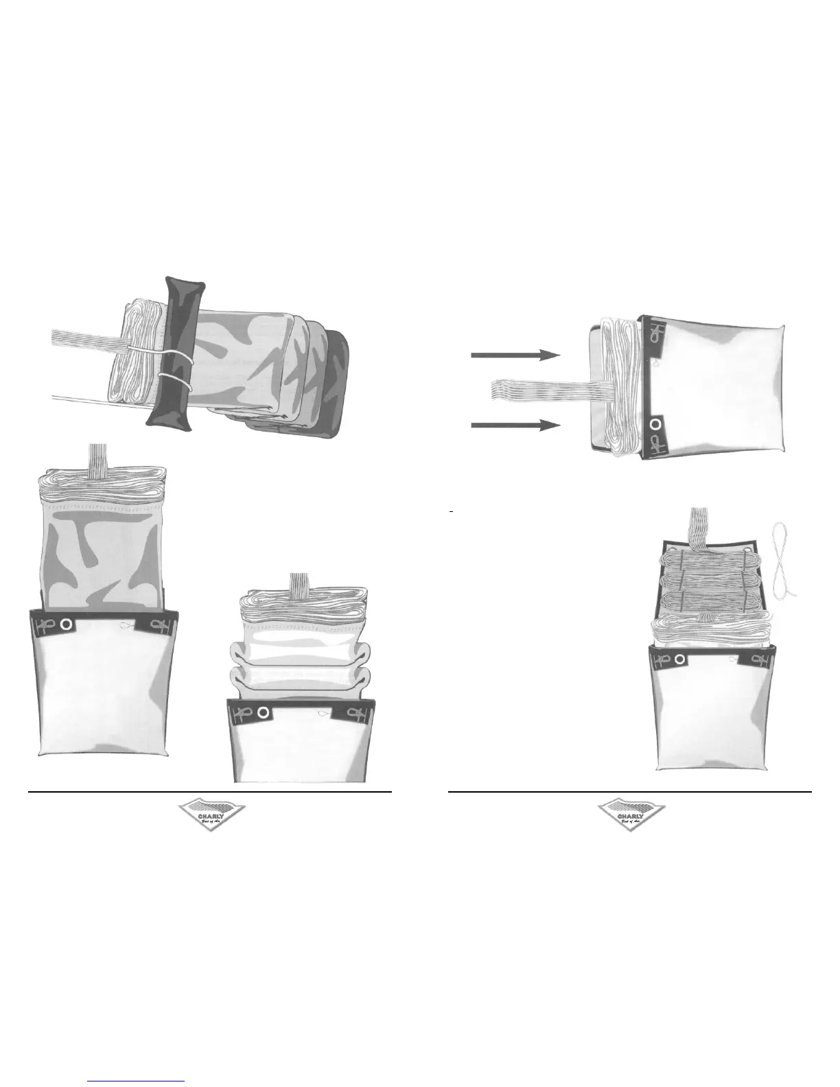
The canopy is placed info the inner
container as shown in gures 8, 9 &
10.
Important: The last 50cm of the canopy
are put into the inner conlainer to look
like an accordion. This part of the canopy
needs to be the rst to slip out of the
inner container during an emergency
opening.
7.Der Schirm wird gemäß Abb.8,
9 &10 in den lnnencontainer
eingelegt.
WICHTIG: Die letzten 50cm. der
Schirmkappe werden einer Ziehharmo-
nika gleich in den oberen Teil des lnnen-
containers gelegt.
Dieser Kappenbereich muß bei einer
Notöffnung als Erster aus dem Innen-
container rutschen!
Abb. 8
Abb. 9
Abb. 10
8.Der Basisrand wird nun oben im Innencontainer aufgestellt, so daß im Notfall die Luft optimal in die Kappe
strömen kann (Abb. 11).
The periphery is now placed into the top ot the inner container, in such a way that the air can stream into the
canopy when the reserve is thrown. (Figure 11)
9. Die Fangleinen werden jetzt gemäß Abb.12 in 8er
Schlaufen zu drei Bündeln zusammengeschlauft und
mit Packgummis (erhältlich bei der Fa. Charly Produkte)
zusammengefasst.
Die restlichen 50cm. der Fangleinen werden zum Verschlie-
ßen des Containers verwendet. Die Reihenfolge des Ver-
schliessens sieht wie folgt aus:
Zuerst wird das mittlere Packgummi durch die links dane-
ben angebrachte Öse geführt, und somit der Innencontainer
zusammengerafft. Nun das Packgummi durch die mittlere
Öse des Innencontainerdeckels führen und die erste Fang-
leinenschlaufe durch das Packgummi ziehen. Die rechts
und links am Innencontainer angebrachten Packgummis
werden nun gemäß Abb. 13 durch die gegenüberliegenden
Deckelösen geführt. Es wird nun jeweils eine Fangleinen-
schlaufe durch die Packgummis gezogen (nicht weiter als
2cm. !! ) Abb.13
The suspension lines are now placed into three bund-
les of gure eighbs, as shown in gure 12 and are held
in place using special rubber bands (available from Charly
Produkte).
The last 50 cm of suspension lines are used to close the
container.
The inner container is closed in the following order:
First pull the left eyelet towards the middle rubber band.
Thread the rubber band through the eyelet, thereby gathe-
ring the inner container together. Now thread the rubber
band through the middle eyelet of the inner container lid
and pull one loop of suspension lines through this rubber
band. The right and left rubber bands on the inner container
are threaded through the eyelets on the lid on the opposite
side, as shown in Figure 13.
Now place a loop of suspension lines through each of the
rubber bands (not more than 2 cm. !!).
 Loading...