Do you have a question about the Chen Hsong Ai-02 and is the answer not in the manual?
Details the product's design, technology, and compliance with standards.
Lists the key functionalities and capabilities of the system.
Compares the features of the Ai-02 with the Ai-01 model.
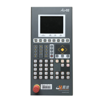
Overview of the computer's main display and control interface.
Explains keys for operation modes and forming conditions.
Details numeric keypad and navigation keys for data entry.
Explains emergency stop, start buttons, and power requirements.
Steps for powering on and initializing the computer system.
Instructions for configuring and operating the system in normal mode.
How to view and analyze the machine's operational cycle data.
Configuration parameters for the mould opening process.
Configuration parameters for the mould closing (clamping) process.
Settings for mould clamping force and injection pressure.
Detailed configuration for the injection process stages.
Parameters for controlling the pressure holding stage of injection.
Configuration for screw plasticizing and back pressure.
Instructions for setting up the automatic purge function.
Parameters for controlling the ejector mechanism.
Configuration for the carriage movement and its stages.
Settings for the air blowing function during mould opening.
Parameters for the first core pulling function (Core A).
Parameters for the second core pulling function (Core B).
Parameters for the third core pulling function (Core C).
Configuration of various timer functions within the system.
Setting parameters for counter functions.
Configuration of temperature deviation alarms for different stages.
Settings for hot runner temperature control for multiple zones.
Configuration of various operational functions and modes.
Options for selecting and managing mould data.
Displays and monitors statistical production data.
Interface for monitoring the status of various system timers.
Interface for monitoring the status of various counter functions.
Displays the status of all input signals to the computer.
Displays the status of all output signals from the computer.
Monitors the status of internal relays within the system.
Allows monitoring of internal program logic and relay states.
Shows the injection termination position and average values.
Displays and allows comparison of injection speed curves.
Displays and allows comparison of injection pressure curves.
Provides access to help information for various functions.
Configuration for system language and current time.
Configures the number of stages for different machine actions.
Defines the ramp (slope) settings for speed and pressure changes.
Configures the output settings for Speed 1.
Configures the output settings for Pressure.
Configures the output settings for Back Pressure.
Configures the output settings for Speed 2.
Sets initial operational parameters and decoder origin.
Settings for auxiliary velocity and pressure adjustments.
Configures timer settings for various machine operations.
Additional counter settings.
Configuration of factory default parameters and machine information.
Shows a log of system warnings and alarms.
Settings for network connectivity and system management.
Allows modification of system passwords for security.
Configuration for manual lubrication cycles and alarms.
Settings for adjusting mould thickness and clamping force.
Adjustments for machine speed reduction percentage.
Configuration of maintenance reminders and intervals.
Procedures for resetting initial machine points after power loss.
Explains the meaning and cause of various computer alarms.
How to set and manage temperature control for various stages.
Settings for heat preservation function.
How to select and switch between operating modes.
Setting parameters for position, speed, and pressure.
How to input and adjust figures for forming conditions.
Explains proportional control adjustment for pressure and speed.
Explains the functions of internal computer counters.
Explains the functions and usage of internal computer timers.
Lists and describes the computer's input and output points.
Shows the input connection diagram for the encoder version.
Shows the layout of the I/O board for the potentiometer version.
Circuit diagram for motor and power control (piston pump).
Circuit diagram for motor and power control (SVP).
Diagram of computer I/O board input points for potentiometer version.
Diagram of computer I/O board input points.
Diagram of computer I/O board output points.
Connection diagram for the extension I/O board.
Interface diagram for robot communication (Euromap 67).
| Brand | Chen Hsong |
|---|---|
| Model | Ai-02 |
| Category | Desktop |
| Language | English |