
K
Kathleen JonesJul 30, 2025
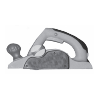
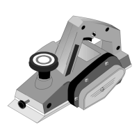
Why does my Chicago Electric Planer leave a rough grain?
- BBarbara KeyJul 30, 2025
If the Chicago Electric Planer stops during operation and produces a rough or fuzzy grain, there are several possible causes. You may be applying too much pressure, so try using less force. The unit might be overloading the circuit; in this case, use it on an isolated circuit. The blade setting could be too deep, so reduce the depth setting and use more passes. Finally, high moisture content in the wood can cause this issue, so ensure the wood is dry before planing.