Page 2 For technical questions, please call 1-800-444-3353. SKU 34552
ASSEMBLY/MOUNTING
INSTRUCTIONS
Read ENTIRE IMPORTANT SAFETY
INFORMATION section at beginning of
this document including all text under
subheadings therein before set up or use.
The Mini Tire-Changer can be mounted 1.
temporarily in a vise (not included) or
permanently to a secure workbench or surface.
For permanent mounting, use pencil to mark 2.
installation holes. Use mounting hardware
(not included) to mount the Base onto a secure
workbench or stand, making sure that there are
no hidden cables or wiring below installation
surface.
Verify that all hardware (uses 7/16” or 1/2” bolts, 3.
at and lock washers and hex nuts) are secure
and that base is mounted evenly and is level.
Insert Holder (16) into Base and lock together 4.
using the Base Pin (13). See Figure 1.
For temporary mounting to a vise, position the 5.
Base between vise jaws with the Base Pin
accessible from the sides of the vise. Tighten
vise jaws, Use vice jaw guards to prevent
damage to Holder surfaces. See Figure 2.
REMOVING TIRE OPERATION
Remove balancing weights, if any, from rim 1.
edges.
Remove tire valve core to deplete the tire.2.
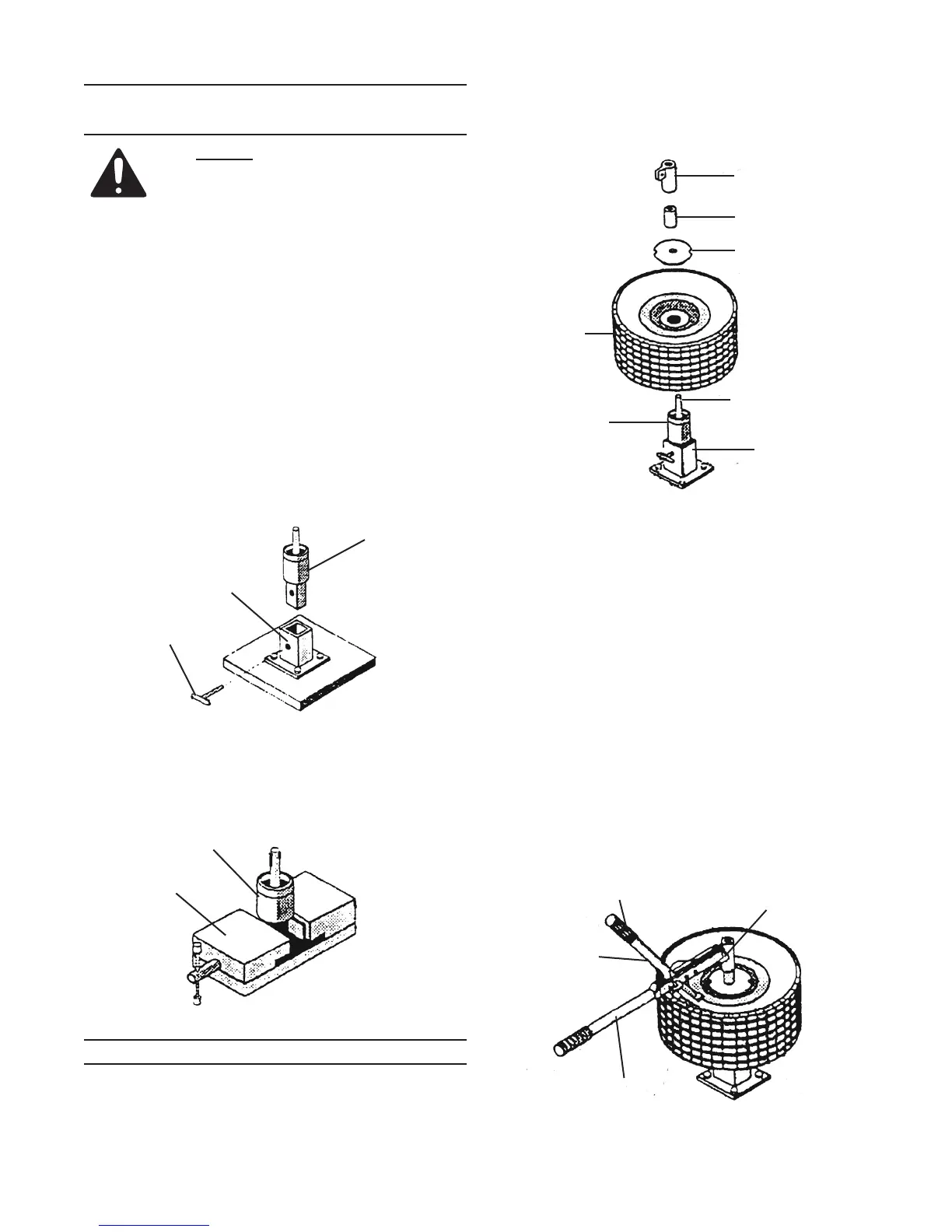
Place tire rim over Threaded Shaft (18). See 3.
Figure 3.
Install cone end of the Alignment Disc (1) over 4.
the Threaded Shaft (18).
Place both Spacers (2) over the shaft.5.
Thread the Locking Nut (3) over the Threaded 6.
Shaft (18) and tighten.
Attach the end of the Forcing Handle (5) to the 7.
tab of the Locking Nut (3) using one of the Pins
(6).
Insert Breaker Handle (4) through the slot in 8.
Forcing Handle and attach the rubberized Grip
(12) to the Breaker Handle, making sure that
the nger grip end of the handle is towards the
Locking Nut.
To break tire beads, Breaker Handle foot should 9.
rest horizontally over the tire at edge of rim. (Use
combination of adjustment holes in the Forcing
Handle and Breaker Handle and if required,
remove one of the Spacers). See Figure 4.
Figure 2
Hub Holder (16)
Vise
Figure 1
Holder (16)
Base (15)
Base Pin (13)
Figure 3
Locking Nut (3)
Spacer (2)
Alignment Disc (1)
Tire Assembly
Threaded Shaft (18)
Hub Holder (16)
Base (15)
Figure 4
Breaker
Handle (4)
Forcing Handle (5)
Pin (6)
Grip (12)
 Loading...