CM 2
Mik-El / Chilton Page 4 of 26
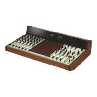
Input Module M1 (and M41)
For this test 1 male and 1 female XLR connectors are required.
Solder pin 2 to 2 and pin 3 to 3. The cable length appropriate to the console size. Screen wire
is not necessary. Plug the female XLR into Aux. 1 output and male XLR into Line input of
M1. (Osc. 1kHz A1 button down only) Adjust A1 master output to 0dBm. (PPM "4" VU -4)
a) Group and channel faders ref. 0dB
b) Pan central
c) Channel to LINE +48v off
d) Set Channel line input gain to 0dB
e) Channel ON
This will give approximately +2dBm (PPM "4 1/2" VU -2dB) on group meters.
Increasing this input level (Master A1 and AFL) by 4dB to +4dB will trip on Channel
LED.
Depressing PFL button will indicate 0dBm on PFL meter independent of Channel
fader.
High pass 70 Hz filter will drop level by 6dB @ 40Hz ref. 1kHz
The EQ section can be checked using spot frequencies 10 kHz for HF 100 Hz for LF
and 100 - 1kHz for Mid.
Microphone Input: Set up as for Line with 0dBm input
a) Pad in.
b) Set channel Mic input gain to 20 dB Control fully anticlockwise
c) Switch channel to MIC
Group meter will now read approximately 0dBm.
Frequency check 40 - 15kHz within 1dB
 Loading...