CR6853
Dec, 2007 V1.1 5/11
Chengdu Chip-Rail Tech. Co., Ltd. http://www.chiprail.com
T
LEB
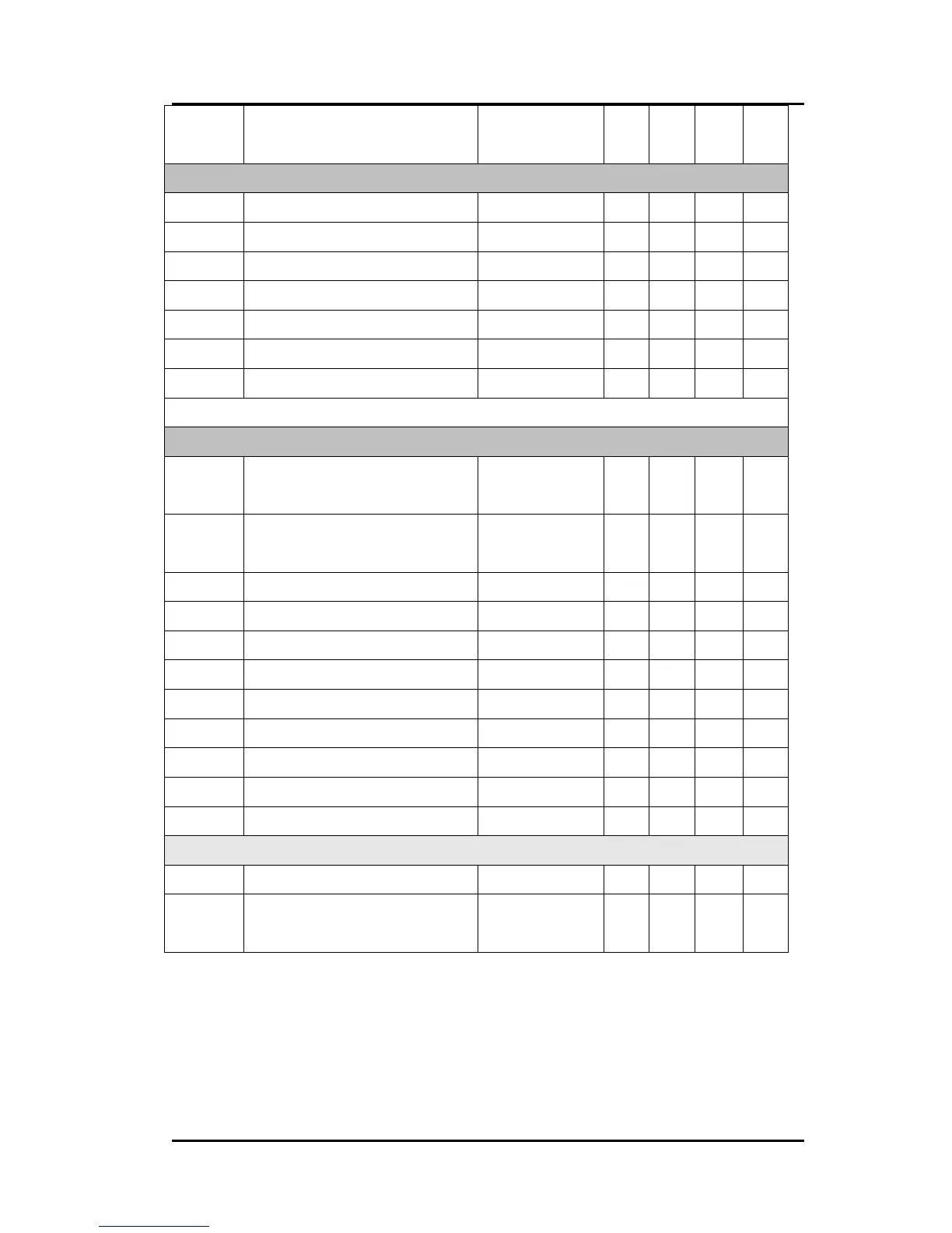
Leading edge blanking time
( LEB )
RI=100K 300
Oscillator (RI Pin)
F
OSC
Normal Frequency RI=100Kohm 60 65 70 KHz
F
PFM
PFM Frequency RI=100Kohm 22 KHZ
Maximum Duty Cycle PWM RI=100Kohm 77 %
DC
MAX
_
F
Maximum Duty Cycle PFM RI=100Kohm 14 %
ΔF
TEMP
Frequency Temp. Stability
-30-100
℃
5 %
T
BLANK
Leading-Edge Blanking Time 300
F
JITTER
Frequency jitter RI=100Kohm -4 4 %
GATE Drive Output (GATE Pin)
V
OL
Output Low Level V
DD
=16V,
I
O
=20mA
0.8 V
V
OH
Output High Level V
DD
=16V,
I
O
=20mA
10 V
T
R1
Rising Time
C
L
=500pF 123
ns
T
F1
Falling Time C
L
=500pF 71 ns
T
R2
Rising Time
C
L
=1000pF 248
ns
T
F2
Falling Time C
L
=1000pF 116
ns
T
R3
Rising Time
C
L
=1500pF 343
ns
T
F3
Falling Time C
L
=1500pF 153
ns
T
R4
Rising Time
C
L
=2000pF 508
ns
T
F4
Falling Time C
L
=2000pF 209
Output Clamp Voltage VDD=20V 18.0
V
Low EMI technique
f
EMI
Low EMI frequency RI=100Kohm 64 Hz
∆f_osc
Frequency modulation range
/Base frequency
RI=100Kohm -3 3 %
 Loading...