8
Connections and Wiring
The rear terminal connections for 1/16 DIN and 1/4
& 1/8 DIN instruments are illustrated in the following
diagrams.
In general, all wiring connections are made to the in-
strument after it is installed. Copper wires must be
used for all connections (except thermocouple signal
wires).
TO AVOID ELECTRICAL SHOCK, AC POWER
WIRING MUST NOT BE CONNECTED TO THE
SOURCE DISTRIBUTION PANEL UNTIL ALL WIR-
ING PROCEDURES ARE COMPLETED.
CHECK THE INFORMATION LABEL ON THE
CASE TO DETERMINE THE CORRECT VOLTAGE
BEFORE CONNECTING TO A LIVE SUPPLY.
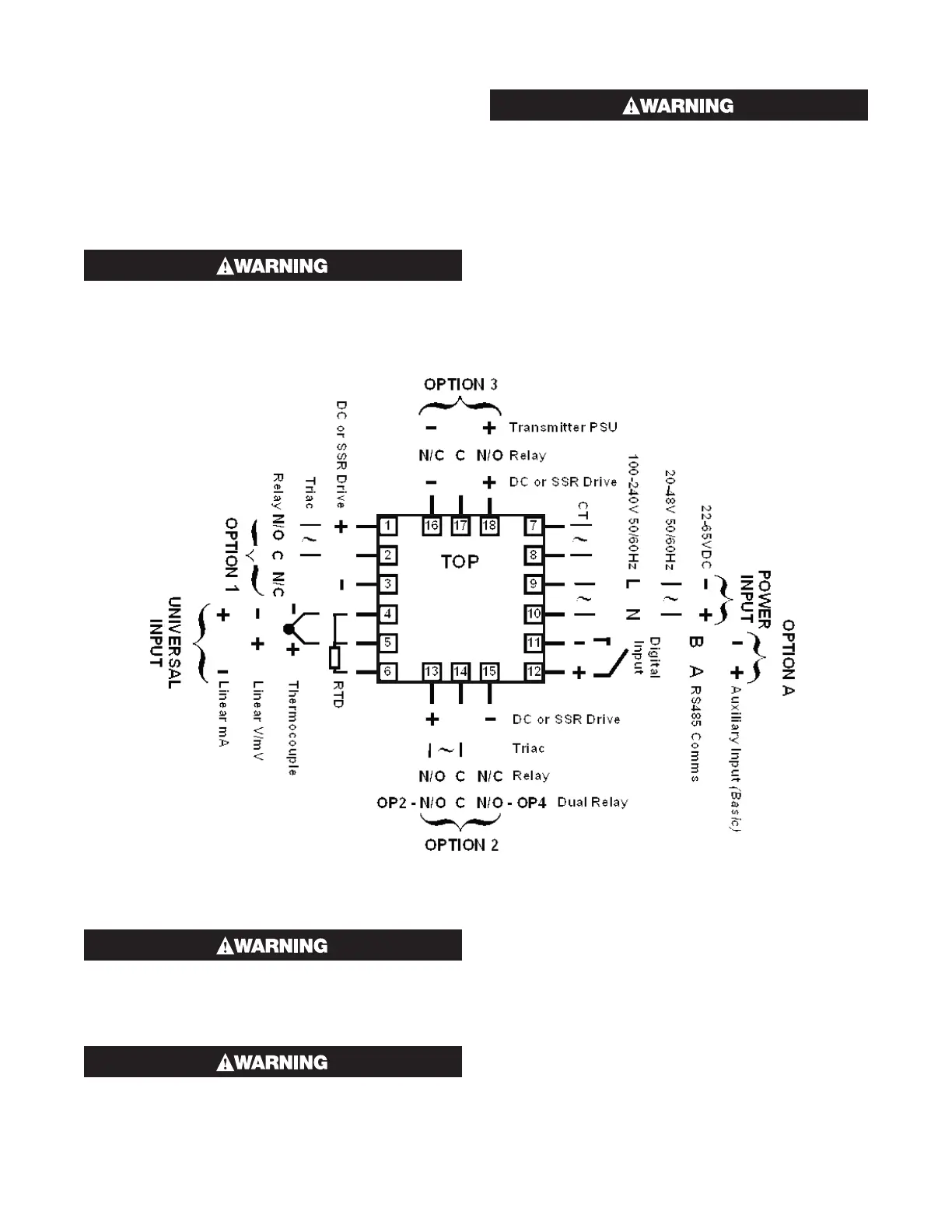
Note: The wiring diagram below shows all possible
combinations. The actual connections required de-
pend upon the features available on the model and the
modules and options fitted.
TO AVOID ELECTRICAL SHOCK, AC POWER
WIRING MUST NOT BE CONNECTED TO THE
SOURCE DISTRIBUTION PANEL UNTIL ALL WIR-
ING PROCEDURES ARE COMPLETED.
CHECK THE INFORMATION LABEL ON THE
CASE TO DETERMINE THE CORRECT VOLTAGE
BEFORE CONNECTING TO A LIVE SUPPLY.
Note: The following wiring diagram shows all possible
combinations. The actual connections required de-
pend upon the features available on the model and the
modules and options fitted.
Figure 11. Rear terminals (1/16 DIN Instruments)
OUTPUT
OUTPUT
 Loading...

