9
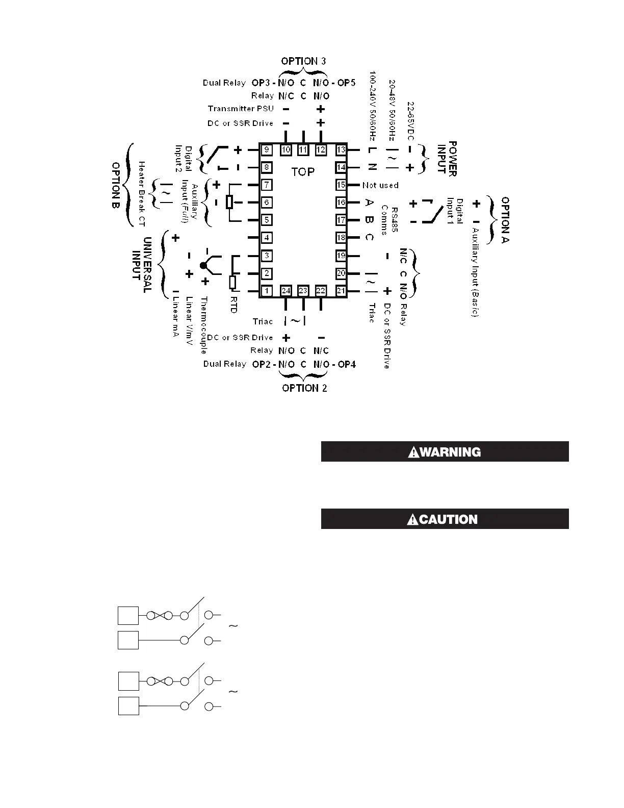
Figure 12. Rear Terminals (1/4 DIN & 1/8 DIN Instruments)
OUTPUT
OUTPUT 1
Power Connections - Mains Powered
Instruments
Mains powered instruments operate from a 100 to
240V (±10%) 50/60Hz supply. Power consumption is
7.5VA. Connect the line voltage (live and neutral) as il-
lustrated via a two-pole isolating switch (preferably
located near the equipment) and a 1amp anti-surge
fuse. If the instrument has relay outputs with contacts
carrying mains voltage, it is recommended that the re-
lay contacts supply should be switched and fused in a
similar manner, but should be separate from the instru-
ments mains supply.
1/16 DIN
1/4 DIN & 1/8 DIN
Figure 13
Mains Power Connections
9
10
13
14
L
N
L
N
CHECK THE INFORMATION LABEL ON THE
CASE TO DETERMINE THE CORRECT VOLTAGE
BEFORE CONNECTING TO A LIVE SUPPLY.
THIS EQUIPMENT IS DESIGNED FOR INSTAL-
LATION IN AN ENCLOSURE THAT PROVIDES
ADEQUATE PROTECTION AGAINST ELECTRIC
SHOCK.
Note: The wiring diagram below shows all possible
combinations. The actual connections required de-
pend upon the features available on the model and the
modules and options fitted.
 Loading...

