11
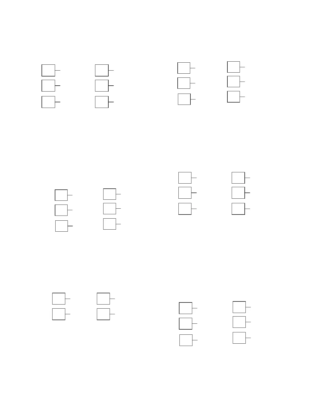
Option Slot 1 – Relay Output Module
If option slot 1 is fitted with a relay output module,
make connections as illustrated. The relay contacts are
rated at 2 amps resistive, 240 VAC (120V max for direct
Valve Motor control).
1/16 DIN 1/4 DIN & 1/8 DIN
Figure 18
Option Slot 1 – Relay Module
19
20
N/C
COM
21
N/O
1
2
N/O
COM
3
N/C
Option Slot 1 - SSR Driver Output Module
If option slot 1 is fitted with an SSR driver output mod-
ule, make connections as illustrated. The solid-state
relay driver is a 0-10V DC signal; load impedance must
be no less than 500 ohms. SSR driver outputs are not
isolated from the signal input or other SSR driver out-
puts.
1/4 DIN & 1/8 DIN
Figure 19
Option Slot 1 - SSR Driver Module
19
20
21
1
2
+
3
_
Option Slot 1 - Triac Output Module
If option slot 1 is fitted with a Triac output module,
make connections as shown. This output is rated at
0.01 to 1 amp @ 280V AC 50/60Hz. (140V max for di-
rect Valve Motor control).
Figure 20
Option Slot 1 - Triac Module
1/16 DIN 1/4 DIN & 1/8 DIN
1
2
∼
20
21
∼
Option Slot 1 - Linear Voltage or mADC
Output module
If option slot 1 is fitted with a DC linear output module,
make connections as illustrated.
Figure 21
Option Slot 1 - Linear Voltage & mADC Module
19
20
_
21
+
1
2
+
3
_
1/16 DIN 1/4 DIN & 1/8 DIN
Option Slot 2 - Relay Output Module
If option slot 2 is fitted with a relay output module,
make connections as illustrated. The relay contacts are
rated at 2 amps resistive, 240 VAC (120V max for direct
Valve Motor control).
Figure 22
Option Slot 2 - Relay Module
22
23
N/C
24
N/O
13
14
N/O
COM
15
N/C
1/4 DIN & 1/8 DIN
Option Slot 2 - SSR Driver Output Module
If option slot 2 is fitted with an SSR driver output mod-
ule, make connections as illustrated. The solid-state
relay driver is a 0-10V DC signal, load impedance must
be no less than 500 ohms. SSR driver outputs are not
isolated from the signal input or other SSR driver out-
puts.
Figure 23
Option Slot 2 - SSR Driver Module
22
23
_
24
+
13
14
+
15
_
1/16 DIN 1/4 DIN & 1/8 DIN
 Loading...

