13
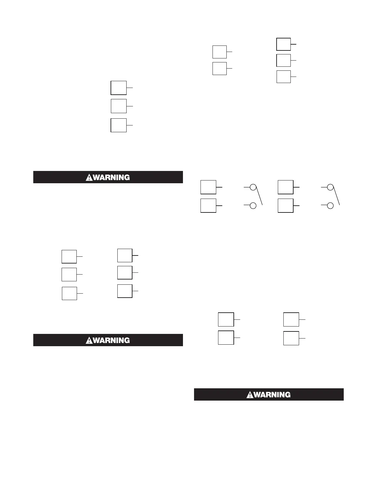
Option Slot 3 - Dual Relay Output Module
If option slot 3 is fitted with a dual relay output module,
make connections as illustrated. This module has two
independent relays, which share a common connec-
tion terminal. The contacts are rated at 2 amp resistive
240 VAC. (120V max for direct Valve Motor control).
Figure 30
Option Slot 3 - Dual Relay Module
Option Slot 3 Dual
Relay is not available
on 1/16 DIN Models
10
N/
12
N/
11
COMMON
1/16 DIN
1/4 DIN & 1/8 DIN
THIS MODULE MUST NOT BE FITTED INTO OP-
TION SLOT 3 ON 1/16 DIN INSTRUMENTS.
Option Slot 3 - Transmitter Power Supply
Module
If option slot 3 is fitted with a transmitter power supply
module, make connections as illustrated. The output is
an unregulated 24V DC, 22mA supply.
Figure 31
Option Slot 3 - Transmitter Power Supply Module
10
11
_
12
+
16
17
_
18
+
1/16 DIN 1/4 DIN & 1/8 DIN
THIS MODULE MUST NOT BE FITTED INTO OP-
TION SLOT 2.
Option Slot A Connections - RS485 Serial
Communications Module
If option slot A is fitted with the RS485 serial communi-
cation module, connections are as illustrated. Carefully
observe the polarity of the A (Rx/Tx +ve) and B (Rx/Tx
-ve) connections.
11
12
RS485
RS485
16
17
18
COM
Figure 32
Option Slot A – RS485 Serial Communications Module
1/16 DIN 1/4 DIN & 1/8 DIN
Option Slot A Connections - Digital Input
Module
If a digital input module is fitted in option slot A, this
may be connected to either voltage free contacts (e.g.
switch or relay), or a TTL compatible voltage. Connec-
tions are shown below.
Figure 33
Option Slot A – Digital Input Module
16
17
_
+
11
12
+
1/4 DIN & 1/8 DIN
Option Slot A Connections – Basic
Auxiliary Input Module
If option slot A is fitted with a basic auxiliary input mod-
ule, connect as shown. For 1/4-DIN & 1/8-DIN models
it is recommend that the full auxiliary input (Option Slot
B) is used instead, as this has additional features and
leaves option slot A free for other modules.
Figure 34
Option Slot A – Basic Auxiliary Input Module
16
17
_
+
11
12
+
1/16 DIN 1/4 DIN & 1/8 DIN
THIS MODULE MUST NOT BE FITTED IF FULL
AUXILIARY INPUT IS FITTED IN OPTION SLOT B.
 Loading...

