66
6050 & 4050 Limit Controllers -
Operator Mode
This is the mode used during normal operation of the
instrument. It can be accessed from Select Mode, and
is the usual mode entered at power-up.
IN NORMAL OPERATION, THE OPERATOR MUST
NOT REMOVE THE INSTRUMENT FROM ITS
HOUSING OR HAVE UNRESTRICTED ACCESS
TO THE REAR TERMINALS, AS THIS WOULD
PROVIDE POTENTIAL CONTACT WITH HAZARD-
OUS LIVE PARTS.
Set all Configuration Mode parameters and
Setup Mode parameters as required before
starting normal operations.
Navigating in Operator Mode
Press to move between displays.
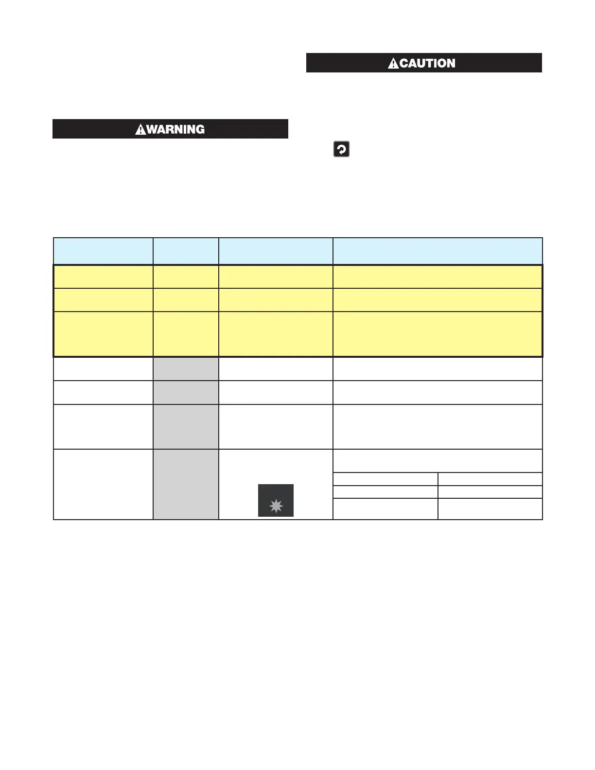
Table 28. 6050 & 4050 Operator Mode Displays
Upper
Display
Lower
Display
When
Visible Description
PV Value Limit SP
Value
Display strategy is set to
EnAb. (Initial Screen)
Process Variable and Limit Setpoint values.
Read only.
Limit SP Value Blank Display strategy is set to
diSA. (Initial Screen)
Limit Setpoint value.
Read only.
SAFE or rSEt
Blank or PV
Value
Display strategy is set to
SAFE. (Initial Screen)
Displays SAFE and blank if Limit Output is not
active. Displays rSEt and Process Variable
value if Limit Output is active.
Read only.
High Limit Hold
HiHd CtrL = Hi in Configura-
tion Mode
Highest PV value since this parameter was last
reset.
Low Limit Hold
LoHd CtrL = Lo in Configura-
tion Mode
Lowest PV value since this parameter was last
reset.
Exceed Time Value
ti
Always available Accumulated time of Limit SP exceed condi-
tions since this parameter was last reset. Time
Format: mm.ss to 99.59, then mmm.s (10 sec
increments) Shows (HH) when ≥999.9
Active Alarm Status
ALSt
When any alarm is
active. ALARM indicator
will also flash
ALARM
Upper display shows which alarm(s) are active.
Inactive alarms are blank
1
Alarm 1 Active
2
Alarm 2 Active
An
Annunciator Active
Note: When an extended Operator Mode is configured the additional parameters are available after the above
parameters. Extended Operator Mode parameters can only be configured using the PC software.
 Loading...

