,
I
t
•
I
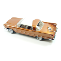
fRONT
DOOR
G;llA~S:S~A~N~D~Ji"""'======="'''''
CHANNEl
ASSY-
VENT
WING
ASSEMBt Y
GLASS
LOWER
CHANNEL
PIVOT
ARM
RETAINER
WASHERS
GLASS
RUN
CHANNEL
ASSEMBlY
-'~
,
y:
____
UPPER
GLASS STOPS
SECTOR
SCREW
NUT
AND tU
~
lOCKWASHER~
.\I
Y.
GLASS
CHANNEl
STOP
BRACKET-lOWER 0 .
REGULATOR
MOTOR
SCREWS
I
SCREW
AND
lOCKWASHER
\
1---GlASS
RUN
CHANNEl
~
VENT
WING
ADJUSTING
SCREW
~
NUT
AND
lOCKW
ASHER
56x117
Fig. 9 - Front Door Gloss Cha nnel
and
Window Lift Assembly
mounting
bracket
to
the
l
eft
or
righ
t.
Tighlen
the
window
lift
motOr mounting
bracket
sc
rews
securely.
I
nstall
trim
panel
and
door
hardware
.
Connect
battery
cable.
REMOVAL
AND
INSTALLATION OF
REAR DOOR SLIDING GLASS
AND
ROTATING GLASS (CAR
EQUIPPED
WITH
ELECTRIC
WINDOW
LIFTS)
Removal
Refer
to
Figure
10
and
proceed
as
follows:
Di
sconnect
t.he
battery. Lower
the
door win-
dow.
Remo
ve
door
hardware
and
trim
panel.
Loosen
glass
lower
~top
SC
I'CWS
and
lower
the
slops
fo
r
clearance.
Remove
outside
belt
line
moulding.
Refer
to
"Replacement of Outside
Belt Line Moulding
Weatherstrip."
Remove and
unhook remote control assembly to provide ac-
cess
to
pivot
bearing
bl'uckct
scr
ews.
RemovinQ
the
RotalinQ
Glass
- Remove door
handle
as outlined in "Outside Door
Handle-
Removal and
In~tallation."
Remove
the
pivot
step
bolt
and
pull
out
the
rotating
glass, Fig-
ure
10.
R
emovinQ
tbe
SlidinQ
Glass
- Remove
the
gla~s
upper stops
and
loosen window
lift
motor
75
Fi
g. 10 - R
emo
ving or Instolling Reor Door Reor Gloss
mounting bracket screws to relax tension
on
the
window
regulator
arms. Remove
retainer
wash-
ers
C"
om
the
window
regulator
arms
and dis-
engage the arms. Remove the shoulder
studs
holding the glass
run
channel assembly. There
are
two shoulder
studs
on
each side of window
in
front
of outside belt line moulding support.
Tilt
the
sliding glass backward and remove
through
the door glass opening.
 Loading...