•
FUEL
SYSTEM 14 - 5
Once the
heaters
have
cycled, the
Wait
to Start
light
goes
out.
While
the engine is cranked, the
heat-
ers are not energized.
POST-HEAT
CYCLE
After
the engine has
been
started, the
post-heat
cy-
cle
will
begin if intake manifold air temperature was
15°C
(59°F)
or below when the
ignition
switch was
turned on. Depending upon intake manifold temper-
ature, either both
heaters
are energized or they are
cycled
on and off (when one is energized, the other is
not).
The time the
heaters
are energized
depends
upon intake manifold air temperature. Refer to the
Air
Intake Heater Cycle Chart.
AIR
INTAKE
HEATER CYCLE
CHART
Intake
Manifold
Tonqporafwo
Preheat
€f€i®
Wmm
Ignition
ICoy
ON
Inglno
Net Running
Pottheot
Cycle
Ignition
Key OH
Engine
tanning
Above
15 °C
(59 °F)
0 Seconds
No
-8
°C(18°F)to
15 °C (59 °F)
10
Seconds
Yes
-17°C(1
°F)
-9
°C(16°F)
15 Seconds
Yes
-26
°C
(-15°F)
to-18°C
(0
°F)
17.5 Seconds
Yes
Below -26 °C
(-15 °F)
20 Seconds
Yes
J?:
14-239
OVERDRIVE
SOLENOID—ENGINE
CONTROLLER
OUTPUT
The overdrive solenoid is
used
on vehicles that
have
an automatic transmission. The solenoid is op-
erated by the engine controller. It controls
shifting
in
and out of overdrive through the overdrive solenoid.
Refer to Group 21 for overdrive solenoid service.
SPEED
CONTROL-ENGINE
CONTROLLER
OUTPUT
The
speed
control vacuum and vent solenoids are
operated by the engine controller. The vacuum sole-
noid
maintains vacuum at a required
pressure
to re-
sume,
set or
accelerate
the
speed
control system. The
vent solenoid allows vacuum to bleed off during de-
celeration, when the
brakes
are applied or the trans-
mission
is shifted into park or neutral.
SCI
RECEIVE
and SCI TRANSMIT—ENGINE
CONTROLLER
OUTPUT
The serial communication interface (SCI) receive
and transmit outputs allow the engine controller to
communicate
with
the
DRBII
diagnostic
tool.
WAIT-TO-START
LAMP-ENGINE
CONTROLLER
OUTPUT
The wait-to-start lamp is turned on and off by the
engine controller
based
on the
charge
air tempera-
ture
sensor
input.
The
light
is turned on when the
ignition
is
first
ac-
tivated.
It
will
remain on for two
seconds
as a bulb
test.
If the engine controller
reads
intake manifold
air
temperature below 15°C
(59°F),
it
will
turn the
wait-to-start
light
on for the intake
heater
preheat
cycle.
The
light
stays
on
until
the
preheat
cycle is
over.
The wait-to-start
light
will
flash on and off if the
charge
air temperature
sensor
input to the engine
controller
is below minimum value or
above
maxi-
mum
value. The engine controller
stores
a fault
mes-
sage
when
these
condtions occur.
WATER-IN-FUEL
LAMP-ENGINE
CONTROLLER
OUTPUT
The water-in-fuel lamp is turned on and off by the
engine controller. The lamp is turned on by the con-
troller
when it
receives
an input
from
the water-in-
fuel
sensor.
The
sensor
sends
an input to the engine
controller
when it
detects
water in the fuel/water
separator
filter.
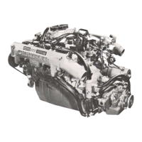
KSB SOLENOID
The KSB solenoid is not an output of the engine
controller.
The solenoid is located on the injector
pump (Fig. 10). It contains a valve that controls
venting
of the injection pump internal
pressure
reg-
ulator. When voltage is supplied to the solenoid, it
closes
off the vent
circuit
in the injection pump.
When
the vent
circuit
is closed off, internal pump
pressure
increases
and injection
timing
advances.
The KSB solenoid allows the injection pump
timing
to
reach
full
advance
sooner.
When
the KSB solenoid is energized, internal
pump
pressure
reaches
8
bars
(116 psi). When the so-
lenoid
is not energized, internal pump
pressure
should be approximately 4
bars
(58 psi).
The KSB solenoid
circuit
contains an air tempera-
ture switch and a 3 ohm resistor. The resistor drops
battery voltage to 10 volts. Battery voltage is sup-
plied
to the solenoid through the
ignition
switch.
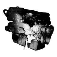
The air temperature switch is mounted on the in-
take manifold next to the
charge
air temperature
sensor
(Fig. 11). The air temperature switch is open
at or
above
16°C
(60°F).
The switch is
fully
closed at
or below 12°C
(54°F).
SYSTEM
OPERATION
IGNITION
SWITCH
ON
When
the
ignition
switch is put in the ON (run)
position
the
following
occurs:
 Loading...