Ill
CONDITIONING
(5.9L
DIESEL)
24 - 1
CONTENTS
page page
COMPRESSOR OVERHAUL
(SD-709)
1 TORQUE
SPECIFICATIONS—A/C
COiPRESSOR
.........
S
COMPRESSOR
OVERHAUL
(SD-709)
INDE1
page
Compressor
2
Compressor
Isolation
1
Compressor
Shaft
Seal
5
Cylinder
Head/Valve
Plate
...................
8
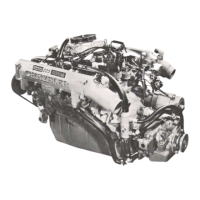
DESCRIPTION
The
A/C system
uses
a
Sanden compressor.
This
compressor
is a 7
piston design. Designated the SD-
709,
the
compressor
is
mounted
on the
front right
side of the
engine
and is driven by
a
serpentine belt.
System lubrication
is
provided
by
135cc
±15cc
(4.6
cu.
in. ±0.5 cu. in.) of 500 viscosity refrigerant oil.
The
clutch used on the compressor consists of
3
ba-
sic
components: the pulley, front plate and the field
coil.
The pulley and field coil
are
attached
to the
front head of the compressor with tapered snap rings.
The
hub
is
keyed
to
the compressor shaft and
is
re-
tained
on the
shaft with
a
self-locking nut. Special
service
tools
are required
to
remove and install
the
clutch
plate on the compressor shaft.
COMPRESSOR
ISOLATION
It
is not necessary to discharge the system for com-
pressor
removal.
The compressor can be isolated from
the remainder of the system and eliminate the need
for recharging when performing compressor service.
(1) Connect pressure
gauge
and manifold.
(2) Close both
gauge
hand valves.
(3) Mid-position both service valves.
WARNING:
USE
EXTREME
CAUTION
WHEN
THE
ENGINE
IS
OPERATING-
DO NOT
STAND
IN A DI-
RECT
LINE
WITH THE FAN. DO NOT PUT
YOUR
HANDS
NEAR
THE
PULLEYS, BELTS
OR FAN. DO
NOT
WEAR
LOOSE
CLOTHING.
(4)
Start
the
engine
and operate the air condition-
ing system.
page
Description
1
Magnetic
Clutch
. 2
Purging
Compressor
of Air 1
(5)
Turn
the suction service valve slowly clockwise
toward
the front
seated
position.
(6) When pressure drops
to
zero,
stop
the
engine
and
compressor and quickly finish front-seating
the
suction service valve.
(7) Front-seat the discharge service valve.
(8) Loosen the oil level check plug slowly to release
any
internal pressure in the compressor.
The
compressor is now isolated from the remainder
of the system.
The
service valves can
be
removed from the com-
pressor.
PURGING
COMPRESSOR
OF AIR
The
compressor must be purged of
air
whenever
it
has
been
isolated for an oil level check or other ser-
vice procedures without discharging
the
entire sys-
tem.
(1)
Cap
the service
gauge
ports on both of the ser-
vice valves.
(2)
Back-seat the suction service valve to allow the
system refrigerant to enter the compressor.
(3) Place the discharge service valve in the mid-po-
sition or cracked-position.
(4) Loosen
the
discharge service valve
gauge
port
cap
to
permit the refrigerant
to
force any air out of
the compressor.
(5) Back-seat
the
discharge service valve
and
tighten the
gauge
port cap.
(6) The compressor
is
now ready for service.
 Loading...