•
EMISSION
CONTROL
SYSTEMS
25
-
1
EMISSION
CONTROL SYSTEMS
EXHAUST
EMISSION
CONTROLS
AIR INLET-DIESEL
ENGINE
The
diesel engine air
inlet
system consists of the:
•
air cleaner housing
•
filter
element
•
air cleaner to turbo-charger
inlet
tube
•
air crossover tube
•
air intake
heaters
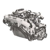
Ambient
air enters the air cleaner housing through
an opening at the bottom of the housing
(Fig.
1). Air
in
the housing is
filtered
by the air cleaner element
(Fig.
2) before it is drawn
into
the turbo-charger.
Fig.
2 Air
Filter
Element
The
turbo-charger
increases
the amount of air
flow
to
the engine. The turbo-charger allows the engine to
use a higher
air-to-fuel
ratio.
This results in im-
proved
emissions.
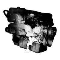
Air
flows
from
the turbo-charger
into
the inter-
cooler
(Fig.
3).
Air leaves the inter-cooler,
passes
through
the air intake
heaters
and enters the intake
manifold.
TURBOCHARGER TURBOCHARGER
INTERCOOLER J9114-238
Fig.
3
Diesel
Inter-Cooler
AIR
INTAKE
HEATER-DIESEL
ENGINE
The
air intake heater warms intake air before it
enters the
manifold.
If intake
manifold
air tempera-
ture
is below 16°C
(60°F)
the engine controller
will
energize the
heaters
through the air intake heater
relays for startup and
initial
warmup.
Refer to Group
14,
Fuel Systems in this supplement for Air Intake
Heater operation.
The
heater is located on top
of
the intake
manifold,
below
the air crossover tube
(Fig.
4).
CAUTION:
Do not
energize
the air
intake
heater
re-
lays
more
than
once
per 15
minutes.
If the relays
are cycled and the key is
then
turned
off,
wait
15
minutes
before
turning
the key to the ON
position.
The 15
minute
period
is to
prevent
damaging
the
engine.
 Loading...