EasyManua.ls Logo

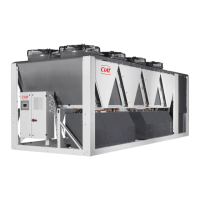
CIAT DYNACIAT POWER LG User Manual

CIAT DYNACIAT POWER LG
32 pages
To Next Page IconTo Next Page
Page #1 background imageLoading...
Page #1 background image
07 - 2023
EN7525593-02
DYNACIAT
POWERâ„¢
LG - LGP
Instruction manual

Questions and Answers:

CIAT DYNACIAT POWER LG Specifications

General IconGeneral
RefrigerantR134a
TypeAir-cooled chiller
Power Supply400V/50Hz
DimensionsVaries significantly depending on the model. Refer to specific model documentation.
Cooling Capacity270 to 1600 kW

Summary

1 - INTRODUCTION

2 - TRANSPORTING THE UNIT

Guidelines for securely strapping and handling the unit during shipment.

3 - RECEIPT OF GOODS

3.1 - Checking the Equipment

Instructions on inspecting the unit for damage or missing components upon delivery.

3.2 - Identifying the Equipment

How to identify the unit using its name plate and associated markings.

4 - SAFETY INSTRUCTIONS

General Safety Precautions

Essential safety precautions to consider during installation, start-up, and adjustments.

5 - MACHINE COMPLIANCE

Declaration of Conformity

Reference to the "Declaration of conformity" document for machine compliance.

6 - WARRANTY

Warranty Period and Terms

Information regarding the warranty period and its effective dates.

7 - UNIT LOCATION

Installation Site Requirements

Requirements and checks for selecting a suitable installation location for the unit.

8 - HANDLING AND POSITIONING

Lifting and Positioning Instructions

Detailed instructions and precautions for safely lifting and positioning the unit.

9 - LOCATION

9.1 - Location of the Unit

Details about unit placement, dimensions, and ground mounting requirements.

9.1.1 - Dimensions and Ground Mounting

Specifications for unit frame dimensions and ground mounting requirements.

9.1.2 - Anti-vibration Mounts (Optional)

Guidance on installing optional anti-vibration mounts for the unit.

10 - OPERATING LIMITS

10.1 - Operating Range

Graphical representation of the unit's application area under full load.

10.2 - Operational Limits

Table detailing operational limits for water-cooled condensers and evaporators.

10.3 - Evaporator Limits

Curves showing allowable temperature differences for chilled water or glycol.

10.4 - Minimum/Maximum Water Flow Rates

Table specifying the minimum and maximum water flow rates for exchangers.

11 - LOCATION OF MAIN COMPONENTS

Component Layout Diagrams

Diagrams showing the layout of major components within the unit.

12 - MAIN COMPONENTS OF THE REFRIGERATING CIRCUIT

Compressor Description

Information on the type of compressors used and their lubrication.

Refrigerant and Oil Details

Information on refrigerant type (R410A) and compressor oil.

Heat Exchangers and Dryer

Description of heat exchangers, expansion valves, and the dehumidifier filter.

Liquid Sight Glass Function

Function and interpretation of the liquid sight glass for monitoring refrigerant.

13 - HYDRAULIC CONNECTIONS

13.1 - Connection Diameter Specifications

Table detailing connection diameters for chilled and cooling water circuits.

13.2 - Optional Flange/Victaulic Adapter Kits

Information on optional adapter kits for flange connections to the hydraulic system.

14 - GLYCOL/WATER-MIX ANTIFREEZE PROTECTION

Glycol Concentration Requirements

Guidance on using glycol/water mixtures for antifreeze protection and required concentrations.

15 - ELECTRICAL CONNECTIONS

15.1 - Power Connection Procedures

Details on power connection requirements, voltage ranges, and wiring practices.

15.2 - Remote Control Connections

Instructions for connecting remote control functions to the unit's terminal X1.

Control and Monitoring Connections

Wiring details for fault alarms, setpoint selection, automatic control, and pump monitoring.

16 - CONTROL AND SAFETY DEVICES

16.1 - Electronic Control Module

Description of the CONNECT2 microprocessor-controlled electronic module and its functions.

16.2 - Main Control Functions

Lists the primary functions managed by the electronic module.

16.3 - Safety Device Management

Explanation of how safety devices are managed, triggered, and reset, including pressure controls.

Evaporator Frost and Circulation Protection

How the evaporator is protected against freezing and loss of water circulation.

Compressor and Discharge Protection

Details on internal compressor protection and discharge sensor functions.

Overpressure and Fire Protection

Protection against overpressure, including fire valves and pressure limits.

16.4 - Phase Controller Kit

Functions and components of the optional phase controller kit for phase monitoring.

16.5 - Safety Sensor and Device Locations

Diagram showing the location of various sensors and safety devices on the unit.

Diagrams for Electronic Expansion Valves

Schematic diagrams illustrating component locations for units with electronic expansion valves.

16.6 - Adjusting Control and Safety Devices

Table detailing the adjustment settings for various control and safety devices.

17 - COMMISSIONING

17.1 - Commissioning Procedures

Procedures for system start-up, configuration, and initial operation by a qualified technician.

17.2 - Essential Pre-Start Checks

Critical checks for compressors, hydraulics, refrigerant charge, and operation before system start-up.

Compressor Checks

Checks for correct compressor rotation, discharge temperature, and current.

Hydraulic System Checks

Procedures for adjusting hydraulic flow rates and checking system pressure.

Refrigerant Charge Verification

Steps for checking and adjusting the refrigerant charge for optimal performance.

Negative Temperature Operation

Essential steps for ensuring unit operation in negative temperature conditions.

18 - TECHNICAL AND ELECTRICAL SPECIFICATIONS

Technical Data Table

Comprehensive table of technical and electrical data for the unit models.

19 - SERVICING AND MAINTENANCE

19.1 - Operating Readings for Maintenance

Table for recording operating parameters during maintenance checks.

19.2 - Unit Maintenance and Servicing

General instructions and safety precautions for unit maintenance.

19.2.1 - Safety Instructions for Maintenance

Safety measures to be followed before and during maintenance work.

Noise and Ear Protection

Recommendations regarding noise levels and ear protection for personnel.

Oil Handling Precautions

Precautions for handling and storing refrigeration oils safely.

Refrigerant Safety Information

General safety precautions and information when working with refrigerants.

19.2.6 - Routine Servicing Checks

Routine checks (weekly, monthly) for unit maintenance and servicing.

Annual Maintenance Checks

List of annual inspections and checks to be performed on the unit.

19.2.7 - Compressor Disassembly

Instructions and torque specifications for compressor disassembly and reassembly.

20 - ECODESIGN

EC Regulations and Leak Testing

Information on EC regulations for greenhouse gases and periodic leak testing requirements.

21 - ERMANENT SHUTDOWN

Shutdown and Disassembly Procedures

Procedures and recommendations for shutting down and disassembling the unit for disposal.

Fluids and Materials Recovery

List of fluids and materials to be recovered for treatment or recycling.

WEEE Compliance and Disposal

Information on Waste Electrical and Electronic Equipment (WEEE) compliance and disposal.

22 - TROUBLESHOOTING OPERATING PROBLEMS

Preliminary Troubleshooting Advice

General advice and preliminary checks for diagnosing and resolving operating problems.

Common Faults and Solutions

Table listing common faults, their probable causes, and recommended instructions for resolution.

23 - SCHEMATIC INSTALLATION DIAGRAMS

23.1 - Cooling Installation with Drycooler

Diagram illustrating the cooling installation configuration with a drycooler.

23.2 - Cooling Mode Operation

Schematic diagram for the unit operating in cooling mode (heating and cooling).

23.3 - Heating Mode Operation

Schematic diagram for the unit operating in heating mode (heating and cooling).

Related product manuals