Do you have a question about the CIAT Major Series and is the answer not in the manual?
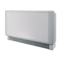
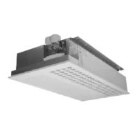
Details of CV, CH models with casing, referring to figure 1 for component identification.
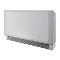
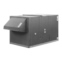
Details of NCV, NCH models without casing, referring to figure 2 for component identification.
Instructions for removing and refitting the unit's casing, with specific steps for different models.
Guidance on installing the unit, covering horizontal and vertical models and mounting requirements.
Procedure for fitting the NCV base accessory, detailing screw types and attachment points as per figure 5.
Steps for fitting the air recovery unit, including securing lugs and blanking panels, referencing figure 6.
Guide to installing CIAT control valves, detailing 2-way and 3-track valve connections and piping as per figure 7.
Instructions for connecting 2-way valves, specifying pipe versions and seal usage for proper installation.
Guidance for installing 3-track valves with bypass, detailing copper piping and different pipe versions.
Guidance on implementing an efficient filtration system on supply and return water lines.
Procedures for flushing the system, including specific steps for thermo and 3-point modulating valves.
Crucial safety step: always disconnect the electrical supply before performing any work on the unit.
Requirement for qualified personnel to perform all electrical installation and maintenance tasks.
Guidance on using supplied circuit diagrams for customer applications, referencing specific figures for system types.
Safety rule: electric heaters must always be assisted by the fan; fan stoppage requires power cut-off to resistors.
Explanation of temperature limit thermostats that protect heating elements from overheating, with causes of reset.
Description of the condensate drain pan's features, including slope, material, drain end piece, and plug.
Critical reminder to refit the plug on the unused side of the drain pan if the hydraulic connection side is switched.
Technical specifications for the condensate drain pump, including maximum flow rate and pipe length limits.
Essential safety procedure: always disconnect electrical and hydraulic supplies before performing maintenance.
Procedures for air filter maintenance for standard and front air recovery models.
Procedures for fan motor assembly maintenance and removal.
Guidance and procedures for cleaning the condensate drain pan.
Importance of a clean heat exchanger coil for unit efficiency and instructions for cleaning with a vacuum cleaner.
Procedure for disassembling the heat exchanger coil due to a leak, including disconnecting components and removing screws.
Information that all units are factory tested and approved, with warranty coverage against manufacturing defects.
Details that CIAT's motor warranty is limited by the supplier's warranty terms.
Critical warning against fitters performing work on the motor, as it invalidates the warranty.
| Brand | CIAT |
|---|---|
| Model | Major Series |
| Category | Air Conditioner |
| Language | English |