M
Mallory EdwardsAug 14, 2025
What causes my CIB UNIGAS Indoor Fireplace to start and lock out?
- NNathan LambertAug 14, 2025
If your CIB UNIGAS Indoor Fireplace starts and then locks out, it could be due to an overload tripped intervention.
What causes my CIB UNIGAS Indoor Fireplace to start and lock out?
If your CIB UNIGAS Indoor Fireplace starts and then locks out, it could be due to an overload tripped intervention.
Why does my CIB UNIGAS Indoor Fireplace turn off and repeat the cycle during operation?
If your CIB UNIGAS Indoor Fireplace turns off and repeats the cycle during operation, the cause may be a fault with the ignition transformer.
Why does my CIB UNIGAS Indoor Fireplace lock out during operation?
Lock-out during operation of your CIB UNIGAS Indoor Fireplace can be caused by a defective minimum gas pressure switch or a dirty gas filter.
What to do if my CIB UNIGAS Indoor Fireplace burner doesn’t start?
If the burner of your CIB UNIGAS Indoor Fireplace doesn’t start, continue with pre-purge because the main switch is open.
What causes my CIB UNIGAS Indoor Fireplace to start and repeat the cycle?
If your CIB UNIGAS Indoor Fireplace starts and repeats the cycle, the thermostats or pressure switches may be defective.
Why doesn’t my CIB UNIGAS Indoor Fireplace switch to high flame?
If your CIB UNIGAS Indoor Fireplace doesn’t switch to high flame, the control box might be faulty.
Why doesn’t my CIB UNIGAS Indoor Fireplace return in low flame?
If your CIB UNIGAS Indoor Fireplace doesn’t return in low flame, it might be due to a defective servocontrol (if provided).
Why is the servo control of my CIB UNIGAS Indoor Fireplace locked and vibrating?
If the servo control of your CIB UNIGAS Indoor Fireplace is locked and vibrating, it could be due to an air pressure switch fault or bad setting.
What to do if my CIB UNIGAS Idea doesn’t start?
If your CIB UNIGAS Burner doesn’t start, several issues could be the cause. First, check that the mains switch is closed. Next, inspect the fuses and replace them if necessary. Also, test the maximum pressure switch for any faults. Verify the auxiliary relay fuses and examine the control box for any issues.
Provides general guidelines, special instructions for burners, and safety advice for installation and use.
Details essential electrical safety measures, earthing, and connection requirements for the unit.
Covers installation for gas, light oil, and heavy oil, including gas safety precautions and directives.
Lists European and national directives and harmonised standards applicable to gas and oil burners.
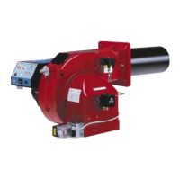
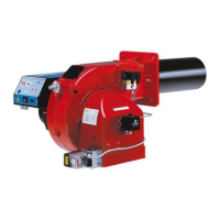
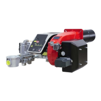
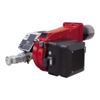
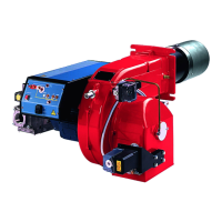
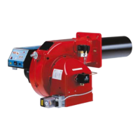
Describes the burner's construction, design features, and model identification system.
Explains how to interpret performance curves and check the gas train size for proper installation.
Details technical specifications, output ranges, fuel types, gas rates, and operating conditions.
Provides overall dimensions and detailed performance curves for various burner models.
Guides on fitting the burner to the boiler, matching, installing the gas train, and electrical connections.
Identifies burner connectors and provides wiring diagrams for different burner types and control systems.
Specific instructions for power supply configurations that do not use a neutral wire.
Explains pressure-flow rate relationships and how to measure gas pressure in the combustion head.
Provides procedures for setting gas and air flow rates, startup output, and combustion parameters.
Details adjustment steps for single-stage, double-stage, progressive, and fully-modulating burners.
Guides on adjusting gas valves for single-stage and double-stage burners, including pressure stabilizer use.
Specific procedures for adjusting progressive and fully-modulating burners, including low flame settings.
Covers calibration of air pressure switches and minimum gas pressure switches.
States the intended use of the burner and warns against improper or dangerous applications.
Details the steps for starting the burner, its operational states, and actions during shutdown.
Outlines recommended maintenance tasks, including filter cleaning, electrode checks, and part greasing.
Provides instructions for removing and replacing filters in the Multibloc valve groups and Krom-Scroeder valve.
Guides on disassembling the burner plate, servicing the fan, and removing/cleaning the combustion head.
Illustrates the correct positioning and gap settings for ignition and detection electrodes.
Explains how to check detection current, stop the burner seasonally, and dispose of the unit.
A comprehensive table listing causes and corresponding troubles for burner operation failures.
Lists available spare parts with their corresponding codes for different burner models.
Provides exploded views and part lists for single-stage and double-stage burner assemblies.
Contains detailed wiring diagrams and a complete key for electrical components and signals.
Details the Siemens LME control box series, its features, and a comparative table.
Describes burner startup preconditions, program sequences, and operational status indications.
Explains control program logic for faults, error code table, and burner control reset procedures.
Lists key technical specifications such as voltage, power consumption, operating conditions, and weight.
| Series | Idea |
|---|---|
| Brand | CIB UNIGAS |
| Combustion Air | Forced Draft |
| Fuel Type | Natural Gas |
| Stages | Single Stage, Two Stage |
| Application | Industrial |