8000 GPRS Cradle Installation
www.cipherlab.com Copyright 2008 CipherLab Co., Ltd.
Power Adapter
P
o
w
er
T
x
/
Rx
L
i
nk
E
S
C
B
S
S
P
1
4
7
2
3
5
6
8
9
A
B
C
D
E
F
G
H
I
JK
L
M
N
O
PQ
RS
TU
V
W
XY
Z
AL
PH
A
FN
0
/*
-
+
$
%
#
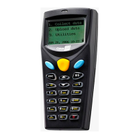
In addition to charging the 8000 Series Mobile Computer, the GPRS cradle is specifically
designed for connecting the mobile computer to WWAN via GPRS or GSM data services.
Please contact your service provider for information on GSM/GPRS data services.
! Dual-Band EGSM900 and GSM1800
! GPRS multi-slot Class 10
! Full PBCCH support
! Comply with GSM phase 2/2+
! Output power — Class 4 (2W) for EGSM900 and Class 1 (1W) for GSM1800
! Power consumption
— GSM Mode: Typical 900 mA (including battery charging)
— GPRS Mode (Class 10): Typical 1200 mA (including battery charging)
Intended Purpose
Installation
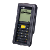
Screw the antenna to the cradle. (Fig. 1) For initial configuration, skip steps 2 and 3.
Remove the rubber cover at the back of the cradle. (Fig. 2)
Insert your SIM card with contacts facing down, and replace the rubber cover. (Fig. 3)
Seat the mobile computer in the cradle. (Fig. 4)
Connect the power supply cord to a suitable power outlet. (Fig. 5)
The cradle's first LED will become red, indicating it is ready for charging the mobile
computer. (Fig. 6)
2
3
4
5
1
Note that you will need pliers to take out your SIM card when it is not desired in use.
SIM C
ar
d
Fig. 1
8000 GPRS Cradle Installation
www.cipherlab.com Copyright 2008 CipherLab Co., Ltd.
Power Adapter
P
o
w
er
T
x
/
Rx
L
i
nk
E
S
C
B
S
S
P
1
4
7
2
3
5
6
8
9
A
B
C
D
E
F
G
H
I
JK
L
M
N
O
PQ
RS
TU
V
W
XY
Z
AL
PH
A
FN
0
/*
-
+
$
%
#
In addition to charging the 8000 Series Mobile Computer, the GPRS cradle is specifically
designed for connecting the mobile computer to WWAN via GPRS or GSM data services.
Please contact your service provider for information on GSM/GPRS data services.
! Dual-Band EGSM900 and GSM1800
! GPRS multi-slot Class 10
! Full PBCCH support
! Comply with GSM phase 2/2+
! Output power — Class 4 (2W) for EGSM900 and Class 1 (1W) for GSM1800
! Power consumption
— GSM Mode: Typical 900 mA (including battery charging)
— GPRS Mode (Class 10): Typical 1200 mA (including battery charging)
Intended Purpose
Installation
Screw the antenna to the cradle. (Fig. 1) For initial configuration, skip steps 2 and 3.
Remove the rubber cover at the back of the cradle. (Fig. 2)
Insert your SIM card with contacts facing down, and replace the rubber cover. (Fig. 3)
Seat the mobile computer in the cradle. (Fig. 4)
Connect the power supply cord to a suitable power outlet. (Fig. 5)
The cradle's first LED will become red, indicating it is ready for charging the mobile
computer. (Fig. 6)
2
3
4
5
1
Note that you will need pliers to take out your SIM card when it is not desired in use.
SIM C
ar
d
Fig. 1
Fig. 2
8000 GPRS Cradle Installation
www.cipherlab.com Copyright 2008 CipherLab Co., Ltd.
Power Adapter
P
o
w
er
T
x
/
Rx
L
i
nk
E
S
C
B
S
S
P
1
4
7
2
3
5
6
8
9
A
B
C
D
E
F
G
H
I
JK
L
M
N
O
PQ
RS
TU
V
W
XY
Z
AL
PH
A
FN
0
/*
-
+
$
%
#
In addition to charging the 8000 Series Mobile Computer, the GPRS cradle is specifically
designed for connecting the mobile computer to WWAN via GPRS or GSM data services.
Please contact your service provider for information on GSM/GPRS data services.
! Dual-Band EGSM900 and GSM1800
! GPRS multi-slot Class 10
! Full PBCCH support
! Comply with GSM phase 2/2+
! Output power — Class 4 (2W) for EGSM900 and Class 1 (1W) for GSM1800
! Power consumption
— GSM Mode: Typical 900 mA (including battery charging)
— GPRS Mode (Class 10): Typical 1200 mA (including battery charging)
Intended Purpose
Installation
Screw the antenna to the cradle. (Fig. 1) For initial configuration, skip steps 2 and 3.
Remove the rubber cover at the back of the cradle. (Fig. 2)
Insert your SIM card with contacts facing down, and replace the rubber cover. (Fig. 3)
Seat the mobile computer in the cradle. (Fig. 4)
Connect the power supply cord to a suitable power outlet. (Fig. 5)
The cradle's first LED will become red, indicating it is ready for charging the mobile
computer. (Fig. 6)
2
3
4
5
1
Note that you will need pliers to take out your SIM card when it is not desired in use.
SIM C
ar
d
Fig. 1 Fig. 2
Fig. 3 Fig. 4 Fig. 5
6
Fig. 6
E
S
C
B
S
S
P
1
4
7
2
3
5
6
8
9
AB
C
D
E
F
G
H
I
JK
L
M
N
O
PQ
RS
TU
V
W
XY
Z
AL
PH
A
FN
0
/*
-
+
$
%#
P
o
w
e
r
T
x
/
R
x
L
i
n
k
Power
Tx/Rx Link
E
S
C
B
S
S
P
1
4
7
2
3
5
6
8
9
AB
C
D
E
F
G
H
I
JK
L
M
N
O
PQ
RS
TU
V
W
XY
Z
AL
PH
A
FN
0
/*
-
+
$
%#
P
o
w
e
r
T
x
/
R
x
L
i
n
k
8000 GPRS Cradle Installation
www.cipherlab.com Copyright 2008 CipherLab Co., Ltd.
Power Adapter
P
o
w
er
T
x
/
Rx
L
i
nk
E
S
C
B
S
S
P
1
4
7
2
3
5
6
8
9
A
B
C
D
E
F
G
H
I
JK
L
M
N
O
PQ
RS
TU
V
W
XY
Z
AL
PH
A
FN
0
/*
-
+
$
%
#
In addition to charging the 8000 Series Mobile Computer, the GPRS cradle is specifically
designed for connecting the mobile computer to WWAN via GPRS or GSM data services.
Please contact your service provider for information on GSM/GPRS data services.
! Dual-Band EGSM900 and GSM1800
! GPRS multi-slot Class 10
! Full PBCCH support
! Comply with GSM phase 2/2+
! Output power — Class 4 (2W) for EGSM900 and Class 1 (1W) for GSM1800
! Power consumption
— GSM Mode: Typical 900 mA (including battery charging)
— GPRS Mode (Class 10): Typical 1200 mA (including battery charging)
Intended Purpose
Installation
Screw the antenna to the cradle. (Fig. 1) For initial configuration, skip steps 2 and 3.
Remove the rubber cover at the back of the cradle. (Fig. 2)
Insert your SIM card with contacts facing down, and replace the rubber cover. (Fig. 3)
Seat the mobile computer in the cradle. (Fig. 4)
Connect the power supply cord to a suitable power outlet. (Fig. 5)
The cradle's first LED will become red, indicating it is ready for charging the mobile
computer. (Fig. 6)
2
3
4
5
1
Note that you will need pliers to take out your SIM card when it is not desired in use.
SIM C
ar
d
Fig. 1 Fig. 2 Fig. 3 Fig. 4 Fig. 5
6
Fig. 6
E
S
C
B
S
S
P
1
4
7
2
3
5
6
8
9
AB
C
D
E
F
G
H
I
JK
L
M
N
O
PQ
RS
TU
V
W
XY
Z
AL
PH
A
FN
0
/*
-
+
$
%#
P
o
w
e
r
T
x
/
R
x
L
i
n
k
Power
Tx/Rx Link
E
S
C
B
S
S
P
1
4
7
2
3
5
6
8
9
AB
C
D
E
F
G
H
I
JK
L
M
N
O
PQ
RS
TU
V
W
XY
Z
AL
PH
A
FN
0
/*
-
+
$
%#
P
o
w
e
r
T
x
/
R
x
L
i
n
k
Specifications
Notifications
Electrical Characteristics
Environmental Characteristics
Certification
Output
AC 100~240 V, 50/60 Hz
— DC 5V, Maximum (peak) 2000 mA
Input —
Operating -10°C ~ 60°C Storage -20°C ~ 70°C
Operating 10% ~ 90% Storage 5% ~ 95%
CE
SRMC, MII
Temperature
Humidity (non-condensing)
Europe
China
LED Status Meaning
Solid red
Off
Flashing green
Off
Flashing green
Solid green
Off
Power ON
Power OFF
Transmitting/receiving data
No activity
Dialing out
Connected
Disconnected
Power
Tx/Rx
Link