English
6 4172332-Ed.01 (2012/07)
Intended use of the pump/installation also includes follow-
ing these instructions.
Any other use is not regarded as intended use.
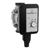
3.2 Product description
The pump (Fig. 1/1) consists of a hydraulic system, a glan-
dless pump motor with a permanent magnet rotor, and an
electronic control module with an integrated frequency con-
verter.
The control module contains an operating knob for setting
the control mode and an LED (Fig. 1/2) for displaying run
and fault signals.
3.3 Functions
All functions can be set, activated or deactivated using the
operating knob.
If the LED is green, mains voltage is applied and the pump
is in operation. If the LED is flashing, the pump is running
outside its normal parameters or is out of operation due to
a fault (see chapter 6, Maintenance / fault).
Control modes
Variable differential pressure (p-v):
The differential-pressure setpoint H is increased linearly
over the permitted volume flow range between ½H and H
(Fig. 2a). The differential pressure generated by the pump
is adjusted to the corresponding differential-pressure set-
point.
3 speed stages:
The pump runs uncontrolled in three prescribed fixed speed
stages. (Fig. 2b).
 Loading...