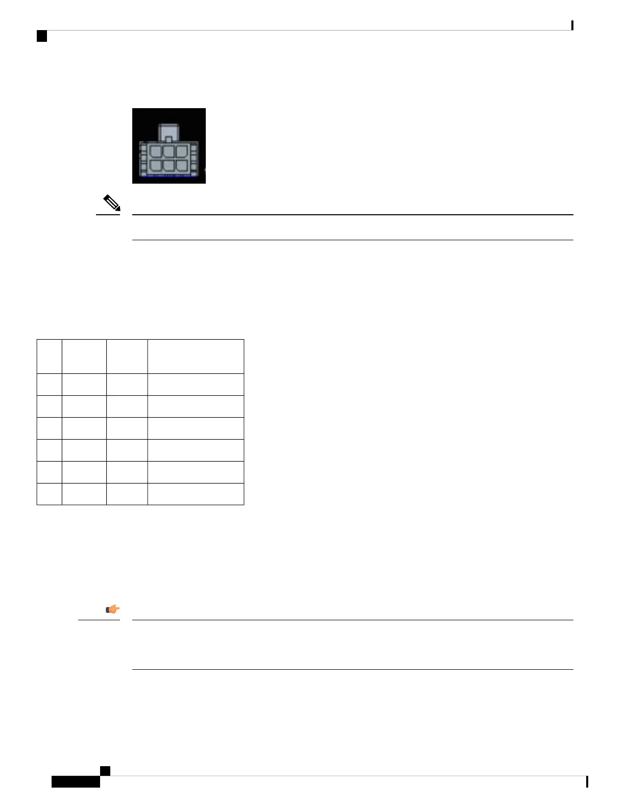
Figure 25: Digital I/O Connector
The default state of the Digital I/O is input, the open-collector is open (off).
Note
The power connector pinouts are as follows:
• Top Row: Pins 6, 5, 4
• Bottom Row: Pins 3, 2, 1
The pinouts for the Digital I/O are described in the following table.
Table 9: Digital I/O Pinouts
DescriptionDirectionNamePin
#
Digital IO Port 3I/ODIGI_IO_11
Ground—GND2
Digital IO Port 2I/ODIGI_IO_33
Digital IO Port 4I/ODIGI_IO_24
Ignition input (6V - 36V)InIgnition5
Digital IO Port 1I/ODIGI_IO_46
Vehicle Connections
When connecting to automotive power, it is expected that the ignition output will be +12 VDC, or +24 VDC
(following the battery voltage). Connect the ignition input of the router to the ignition output of the automobile.
The DC In + and DC In - leads can be directly connected to the battery. However, we recommend that you
connect them after a fuse.
For vehicle installations, it is required to connect the ignition input, and use the Ignition Power Management
feature of the router. This eliminates unnecessary power cycling of the router whenever the vehicle is turned
off and then turned back on.
Important
Cisco Catalyst IR1800 Rugged Series Router Hardware Installation Guide
60
Digital I/O, Ignition, and CAN Bus Connectivity
The Digital I/O Connector
 Loading...


