Statement 1046—Installing or Replacing the Unit
To reduce risk of electric shock, when installing or replacing the unit, the ground connection must always be
made first and disconnected last.
Warning
Before you begin
Before you can ground the chassis, you must have a connection to the earth ground for the data center building.
Step 1 Use a wire-stripping tool to remove approximately 0.75 inch (19 mm) of the covering from the end of the grounding
wire. We recommend 6-AWG wire for the U.S. installations.
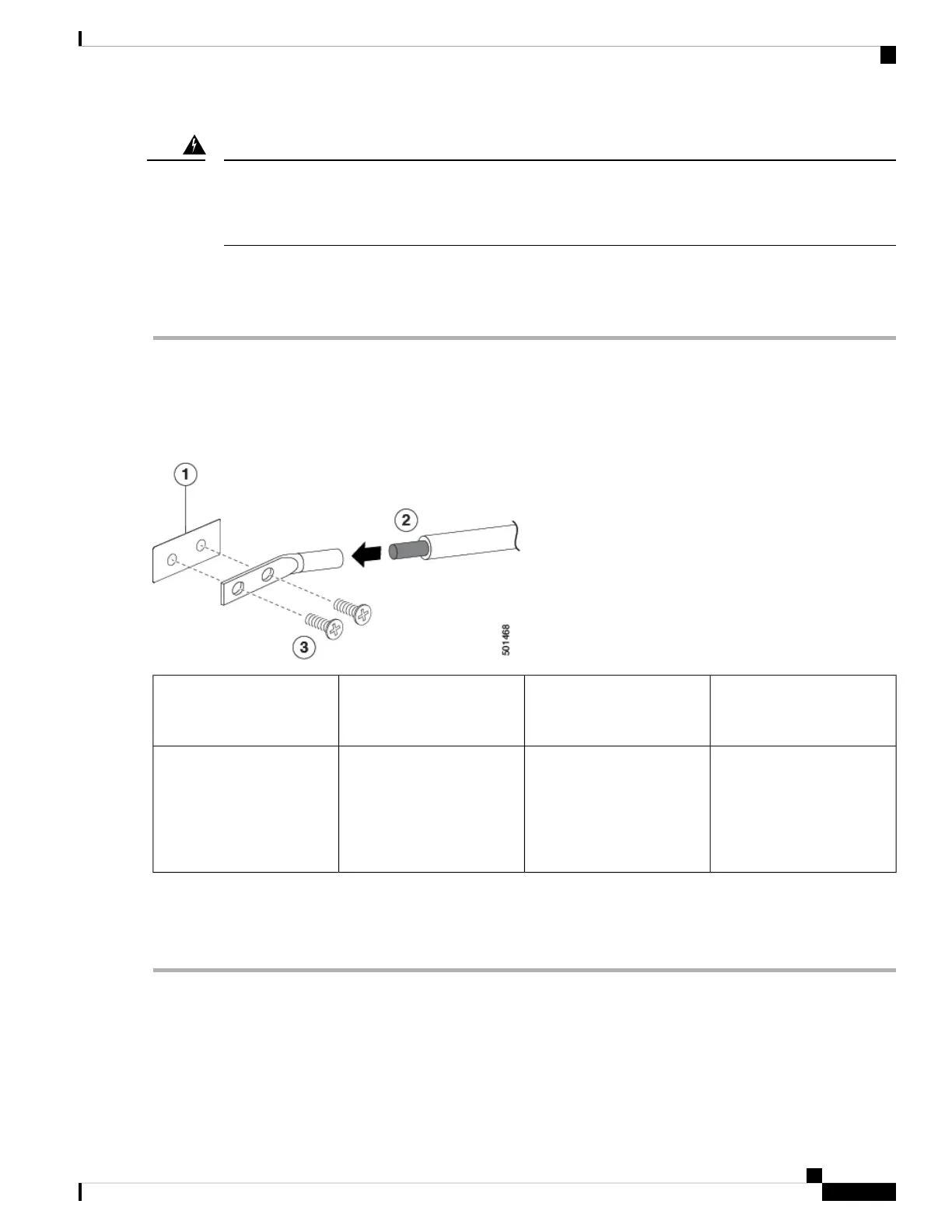
Step 2 Insert the stripped end of the grounding wire into the open end of the grounding lug. Use a crimping tool to crimp the
lug to the wire, see the following figure. Verify that the ground wire is securely attached to the grounding lug by attempting
to pull the wire out of the crimped lug.
2 M4 screws are used to
secure the grounding lug to
the chassis
3Chassis grounding pad1
Grounding cable, with 0.75
in. (19 mm) of insulation that
is stripped from one end,
which is inserted into the
grounding lug and crimped
in place
2
Step 3 Secure the grounding lug to the chassis grounding pad with two M4 screws, see the previous figure. Tighten the screws
to 11 to 15 in-lb (1.24 to 1.69 N·m) of torque.
Step 4 Prepare the other end of the grounding wire and connect it to the facility ground.
Starting the Switch
To power up the switch, follow these steps:
Cisco Nexus 3500 Hardware Installation Guide
21
Installing the Chassis
Starting the Switch
 Loading...