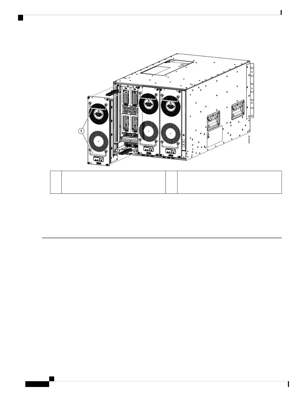
Figure 28: Installing a Fan Tray
Position the alignment pins at the top and bottom
of the fan tray to alignment holes in the chassis and
press the fan tray into the slot.
2Hold both handles with both of your hands.1
c) Screw in each of the four captive screws to secure the fan tray to the chassis and tighten them to 8 in-lb (0.9 N·m)
of torque.
Step 3 Verify that the fan tray is functioning by making sure that its Status LED is green.
For more information about the fan tray LEDs, see the I/O Module LEDs, on page 162 topic.
Migrating from Gen 1 Fan Trays (N77-C7706-FAN) to Gen 2 Fan
Trays (N77-C7706-FAN-2)
Perform the steps given below to replace all the three Gen 1 fan trays in a switch with Gen 2 fan trays:
1. Put the switch in fan tray maintenance mode by using the hardware fan-tray maintenance-mode [long
| medium | short] command.
2. Remove the left-most Gen 1 fan tray, FAN TRAY 1 (N77-C7706-FAN), from the switch.
3. Insert the Gen 2 fan tray (N77-C7706-FAN-2) into the empty fan tray slot.
Cisco Nexus 7706 Hardware Installation Guide
OL-31330-0196
Installing or Replacing Modules, Fan Trays, and Power Supplies
Migrating from Gen 1 Fan Trays (N77-C7706-FAN) to Gen 2 Fan Trays (N77-C7706-FAN-2)

 Loading...


