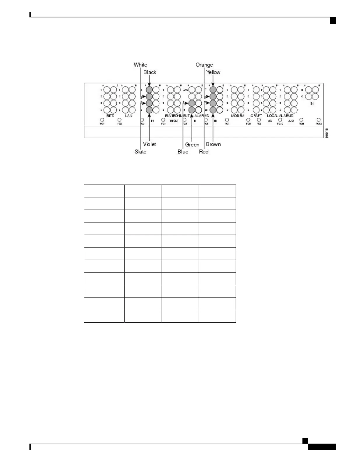
Figure 46: AEP Wire-Wrap Connections to Backplane Pins
The following table shows the backplane pin assignments and corresponding signals on the AIC-I and AEP.
Table 8: Pin Assignments for the AEP
AEP SignalAIC-I SignalBackplane PinAEP Cable Wire
AEP_GNDGNDA1Black
AEP_+5AE_+5A2White
VBAT–VBAT–A3Slate
VB+VB+A4Violet
AE_CLK_PAE_CLK_PA5Blue
AE_CLK_NAE_CLK_NA6Green
AE_DOUT_PAE_DIN_PA7Yellow
AE_DOUT_NAE_DIN_NA8Orange
AE_DIN_PAE_DOUT_PA9Red
AE_DIN_NAE_DOUT_NA10Brown
The following figure is a circuit diagram of the alarm inputs. (Inputs 1 and 48 are shown in the example.)
Cisco ONS 15454 Hardware Installation Guide
87
Installing the ONS 15454 M12 (ANSI and ETSI) Shelf
ONS 15454 ANSI Alarm Expansion Panel

 Loading...


