Silicon Switch Processor (SSP) Installation and Configuration 19
Installing the SSP
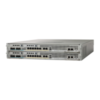
Figure 7 Cisco 7000 Power Supply LEDs
RP LEDs
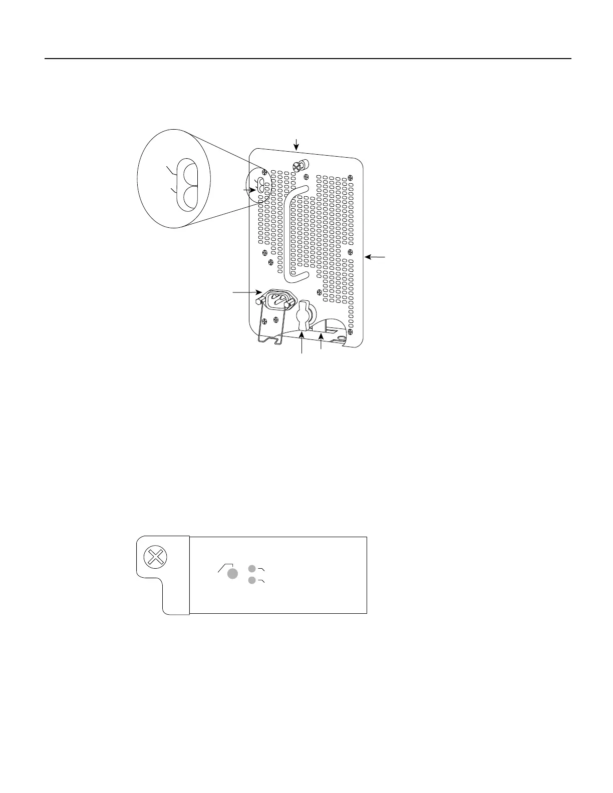
Figure 8 shows the three LEDs on the RP faceplate. These LEDs indicate the system and RP status.
When the router is turned on or restarted, the boot error LED goes on for one or two seconds, then
goes off. The CPU halt LED, which goes on only if the system detects a processor hardware failure,
remains off. If the boot error LED remains on for more than five seconds, the router is unable to boot
and you must restart the router. A successful boot is indicated when the boot error LED goes off;
however, this does not necessarily mean that the system has reached normal operation. During
normal operation, the CPU halt and boot error LEDs are off, and the normal LED is on.
Figure 8 RP LEDs (Horizontal Cisco 7010 Orientation Shown)
I
O
DC FAIL
AC POWER
Power supply
front panel
On/off switch
AC power
receptacle
LEDs
Captive
installation
screw
Locking device
H1314a
DC FAIL
AC POWER
NORMAL
BOOT ERROR
CPU HALT
H2061
 Loading...
