Silicon Switch Processor (SSP) Installation and Configuration 3
Cisco 7000 Series Overview
interface processors slide into slots in the rear of the chassis and connect directly to the backplane.
The backplane slots are keyed so that the SSP or SP, RP, and interface processors are installable only
in the slots designated for them. The SSP inserts into the slot formerly reserved for the SP.
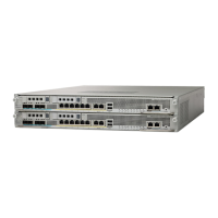
Figure 2 Cisco 7000—Interface Processor End
Figure 3 shows the interface processor end of the Cisco 7010 model, which provides access to the
five processor slots, the AC input receptacle, the power switch, and a power status indicator. When
facing the interface processor end of the chassis, the RP and SP slots are at the top. The three
interface processor slots are numbered from the bottom up beginning with slot 0 (the bottom slot)
through slot 2 (the center slot).
H2358
Slot 0
1
2
3 4 SP
or
SSP
slot
RP
slot
Upper
power supply
Lower
power supply
I
O
DC FAIL
AC POWER
I
O
DC FAIL
AC POWER
Captive
installation screw
Captive
installation screw
 Loading...