- 4 -CJ-763E
051-6451-90 LC74782JMH-9883-TLM
On-Screen Display Controller LSI for VCR Products
LC74782 displays characters and patterns on a TV screen under micro-
processor control.
And LC74782 displays up to 12 lines of 24 characters, each in a 12x18
dot matrix.
Terminal Description
pin 1: VSS 1 : Digital system ground.
pin 2: Xtal IN : Connect the crystal to generate the internal syn-
chronization signal.
Or input an external clock (2fsc or 4fsc).
pin 3: Xtal OUT : Connect the crystal.
pin 4: CTRL 1 : Inputs the crystal/oscillator selection signal.
Low = crystal oscillator mode.
High = external clock mode.
pin 5: BLANK : This terminal outputs the blank signal.
pin 6: OSC IN : Connect the coil and capacitor to form the os-
cillator that generates the dot clock.
pin 7: OSC OUT : Connect the coil and capacitor to form the os-
cillator that generates the dot clock.
pin 8: CHARA : Outputs the character signal.
pin 9: CS : Serial data input is enabled when low.
pin 10: S CLK : Serial data input clock input.
pin 11: S IN : Serial data input.
pin 12: VDD 2 : Analog system power supply.
pin 13: CV OUT : Composite video signal output.
pin 14: NC : Must be either connected to ground or left open.
pin 15: CV IN : Composite video signal input.
pin 16: VDD 1 : +5 V. Digital system power supply.
pin 17: SYN IN : Video signal input for the built-in sync separator
circuit.
pin 18: SEP C : Sync separator circuit bias voltage monitor pin.
pin 19: SEP OUT : Built-in sync separator circuit composite sync sig-
nal output.
pin 20: SEP IN : Inputs a vertical synchronization signal created
by integrating the SEP OUT pin output signal.
pin 21: CTRL 2 : NTSC/PAL-M switching input.
High = PAL-M format.
Low = NTSC format.
pin 22: CTRL 3 : SEPIN input control.
High = V-SYNC not input.
Low = V-SYNC input.
pin 23: RST : System reset input.
pin 24: VDD 1 : +5 V digital system power supply.
051-9402-08 AT93C56W 2k bit EEP-ROM
Terminal Description
pin 1: CS :IN: The chip select command input.
pin 2: S CLCK :IN : Serial clock input.
pin 3: SI :IN: Serial data input.
pin 4: SO : O : Serial data output.
pin 5: GND : - : Ground.
pin 6: ORG :IN: Internal organization to decide the word
length.
pin 7: NU : - : Not in use.
pin 8: VCC : - : Positive supply voltage.
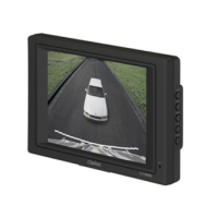
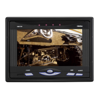
Adjustment of distance mark center position
* When the distance marks are set, press MARK button to
display the distance mark and mark an adjustment men-
tioned in #6.
* When the distance mark is not set up, please perform the
adjustment and the check from #1 to #10.
1. Input the cross-hatch video signals(horizontal H=17, Verti-
cal V=15: Leader test pattern) to the Camera jack.
2. Keep pressing MARK button for more than 2 seconds.
Display content " P0 ".
3. Press CAM1 button.
Display content " P1 ".
4. Press MARK button.
Display content " UD " " P1 ".
5. Press MARK button.
Display content " CAM1 " " 5 " .
6. Adjust TC1 to make the distance between A and B in Fig. 4
to be 2.0mm or less.
7. Keep press MARK button for more than 2 seconds.
Display content " P1 ".
5
Center line
Fig. 4
A
B
8. Please push ON button until "P0" is displayed.(14 times)
Display content " P0 ".
9. Press MARK button.
Display content " UD " " P0 ".
10.Press MARK button.
Display content " CAM1 " " 5 ".
EXPLANATION OF IC
1
2
3
4
Vin 1
Switch
Vin 2
N.C.
8
7
6
5
Buffer
L
H
Ground
Vout
Vcc
N.C.
051-5308-00 NJM2233BM Single 2-input Video Switch
051-1243-00 uPC1379C Synchronization Signal Processor for TV
uPC1379C is bipolar analog IC designed for mono-chrome TV and small
size color TV.
It contains synchronous signal separator, vertical deflection signal gener-
ator, vertical power stage, and horizontal deflection signal generator.
1
2 3 4
6
5
8
15
14
13
12
10
11
9
7
16
Vertical
OSC
12V
Voltage
Booster
Vertical
Output
Synch
Separator
Horizontal
AFC
Horizontal
OSC
Horizontal
Pre-driver
Shunt
Regulator
VCC
Horizontal
AFC
output
Horizontal
OSC
input
Horizontal
Pre-driver
output
Vertical
output
Vertical
Feedback
Power
supply
for
horizontal
section
Vertical Sync input
Synch Separator
input
Horizontal AFC
input
Vertical Synch
Separator output
Vertical blanking signal
adjustment
 Loading...